BUCKLING ANALYSIS IN A CYCLONIC SEPARATOR STAND.
1. Objective:-
i. Have to perform a buckling analysis on a cyclonic separator stand.
ii. Create a metallic stiffener on the legs of the stand and run the analysis to find out the change in the buckling factor of safety.
iii. The next step is to run a design study and find the optimum position for the stiffener.
iv. Compare the results for all the cases using tables and highlight the best one.
2. Basics:-
In engineering, buckling is the sudden change in the shape of a structural component under loads such as the bowing of a column under compression or the wrinkling of a plate under shear. If a structure is subjected to a gradually increasing load when the load reaches a critical level, a member may suddenly change shape and the structure and component are said to have buckled. Buckling may occur even though the stresses that develop in the structure are well below those needed to cause failure in the material of which the structure is composed. Further loading may cause significant and somewhat unpredictable deformations, possibly leading to complete loss of the member's load-carrying capacity. However, if the deformations that occur after buckling do not cause the complete collapse of that member, the member will continue to support the load that caused it to buckle. If the buckled member is part of a larger assemblage of components such as a building, any load applied to the buckled part of the structure beyond that which caused the member to buckle will be redistributed within the structure. Some aircraft are designed for thin skin panels to continue carrying load even in the buckled state.
The theory of the behaviour of columns was investigated in 1757 by mathematician Leonhard Euler. He derived the formula, the Euler formula, that gives the maximum axial load that a long, slender, ideal column can carry without buckling. An ideal column is one that is perfectly straight, made of a homogeneous material, and free from initial stress. When the applied load reaches the Euler load, sometimes called the critical load, the column comes to be in a state of unstable equilibrium. At that load, the introduction of the slightest lateral force will cause the column to fail by suddenly "jumping" to a new configuration, and the column is said to have buckled. This is what happens when a person stands on an empty aluminium can and then taps the sides briefly, causing it to then become instantly crushed (the vertical sides of the can understand as an infinite series of extremely thin columns).[citation needed] The formula derived by Euler for long slender columns is given below.

Where:-
 , maximum or critical force (vertical load on column).
 , modulus of elasticity.
 , the smallest area moment of inertia (second moment of area) of the cross-section of the column.
 , unsupported length of the column.
 , column effective length factor, whose value depends on the conditions of end support of the column, as follows.
For both ends pinned (hinged, free to rotate), K=1.0.
For both ends fixed,  .
.
For one end fixed and the other end pinned, 
For one end fixed and the other end free to move laterally, 
 is the effective length of the column.
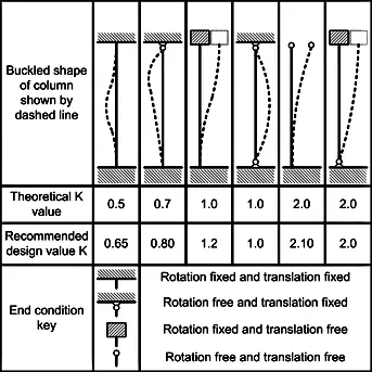
Our problem belongs to the case where For one end fixed and the other end free to move laterally, i.e .
3. Procedure:-
First Importing the file for the cyclonic separator stand and Optimizing the assembly by suppressing the parts for the simulation and saving it as a new part.
The actual cyclonic separator:
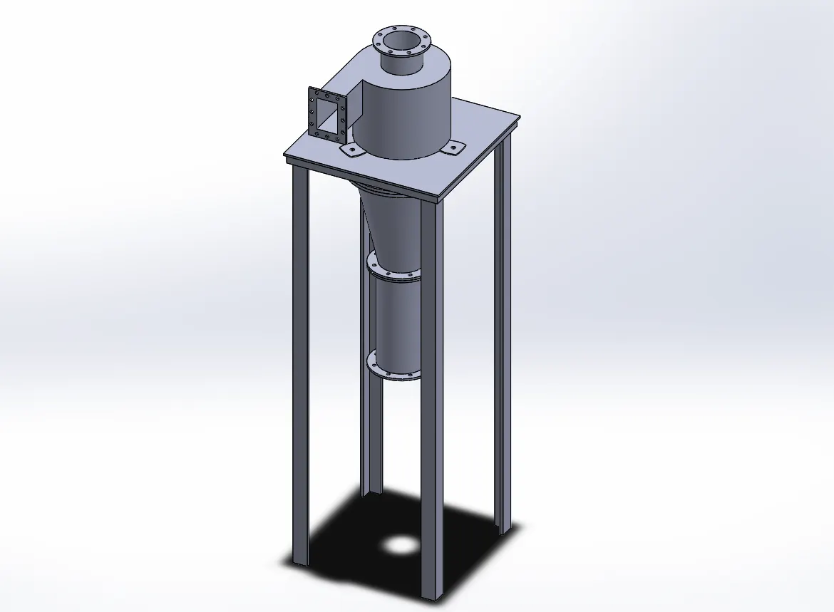
Due to optimizing the part, the simulation results do not change but the calculation time is reduced.
3.1 Cyclone Separator stand without metallic stiffener:
Step-1: Importing the file for the cyclonic separator stand as shown below.
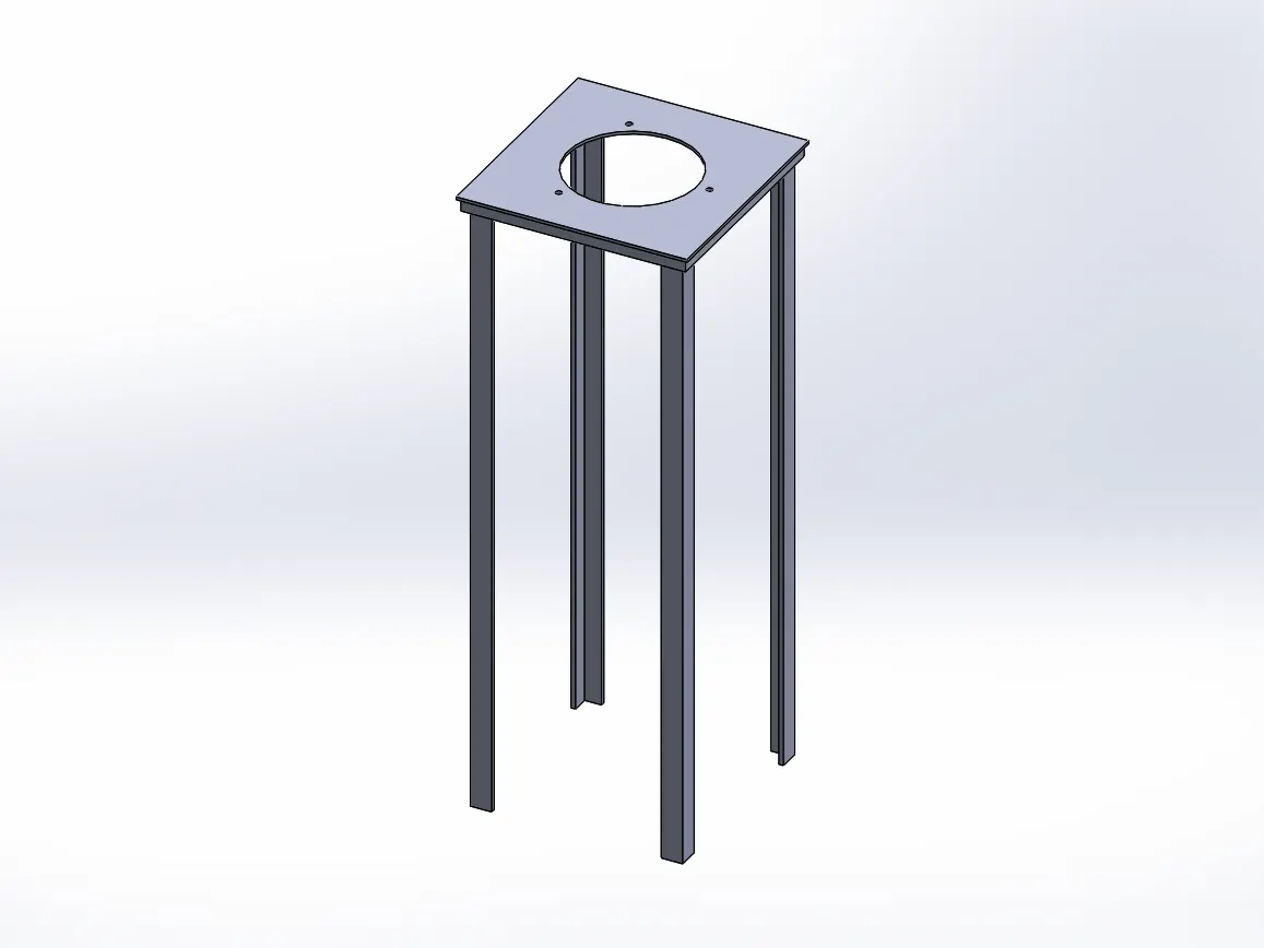
Step-2: Setting up a new simulation study without the use of a stiffener as a Buckling problem.
Step-3: applying material as alloy steel.
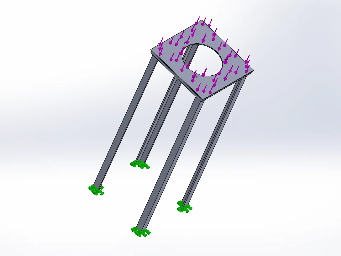
Step-4: Setting Fixtures on one side and applying force on either side as 150 KN as shown below.
Step-5: Defining Mesh as fine size.
Step-6: Run the simulation.
3.1 Cyclone Separator stand with metallic stiffener:
Step-1: Importing the file for the cyclonic separator stand.
Step-2: Creating Stiffener as shown below.
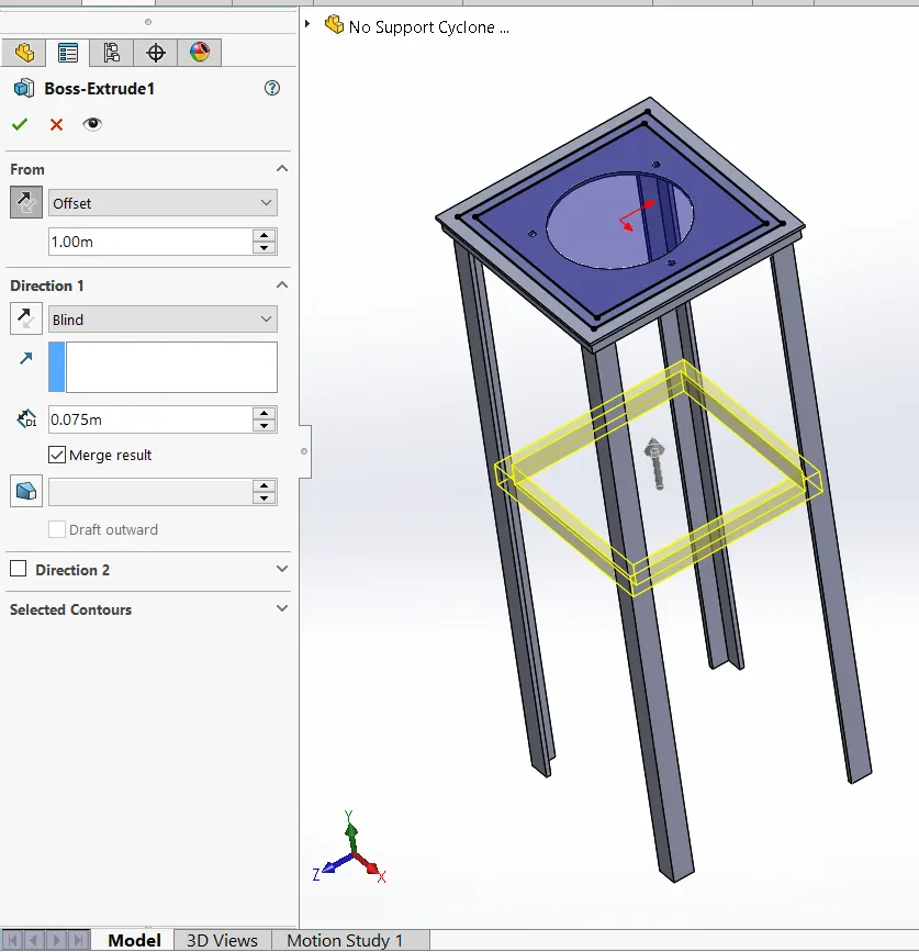
Step-3: Setting up a new simulation study with the use of a stiffener as a Buckling problem.
Step-4: Setting Fixtures on one side and applying force on either side as 150 KN as shown below.
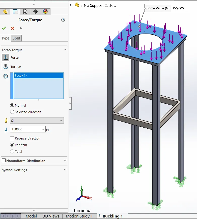
Step-5: applying material as alloy steel same as previous one.
Step-6: Defining Mesh as fine size.
Step-7: Defining the Design study to get the find the optimum position for the stiffener we are varying the position of the stiffener and calculate the buckling accordingly.
Step-8: Select a dimension of the stiffener from base to varying offset distance by defining the variable option available in the study. Defining the min range as 0.25, maximum range as 1.75 and the steps between them are as 0.25m. similarly defining constraints (add sensors -> simulation data-> Buckling factor of safety) as a greater than 25. Defining Goals (max model-> simulation data) as buckling Factor of safety as shown below.
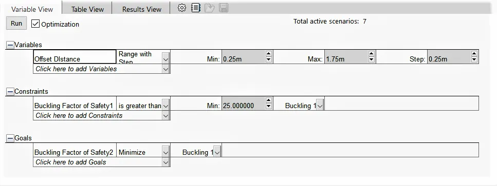
Overall, We have design studies in which FOS is greater than 25 (as defined in the constraints) but out of we have to max the buckling FOS (i.e Defined in the goals). Now we will find the best value based on the constraints and goals provided.
Step-9: Run the simulation.
4. Simulation and Analysis:-
In both cases, we are taken the same material hence the material properties are also the same as shown below.
Material Properties for Both cases:
[Material: Alloy Steel]
| Property | Value | Units |
| Elastic Modulus | 210000 | N/mm^2 |
| Poisson's Ratio | 0.28 | N/A |
| Shear Modulus | 790000 | N/mm^2 |
| Mass Density | 7700 | kg/m^3 |
| Tensile Strength | 723.8256 | |
| Compressive Strength | N/mm^2 | |
| Yield Strength | 620.422 | N/mm^2 |
| Thermal Expansion Coefficient | 1.3e-05 | /K |
| Thermal Conductivity | 50 | W/(m/k) |
| Specific Heat | 460 | j/(kg.k) |
| Material Damping Ratio | N/A |
Other parameters:
| Model Type | Linear Elastic Isotropic |
| Units | SI-N/mm^2 (Mpa) |
| Category | Steel |
| Name | Alloy Steel |
| Default Failure Criterion | Max von Mises Stress |
| Sustainability | Defined |
Case-1 Cyclone Separator stand without metallic stiffener:
In the first case, we simulate the Cyclone Separator stand without metallic stiffener based on the procedure as discussed in the procedure section. here we are applying force on one side and fixing on another side i.e fixing the legs of cyclone separator stand and applying a force of 150 kilonewtons on the top face. after defining the mesh and running the simulation we get the following output.

Where:-
the maximum buckling amplitude is indicated in red while the minimum buckling amplitude is indicated as a blue. the green area indicates the average buckling amplitude.
Case-2 Cyclone Separator stand with metallic stiffener:
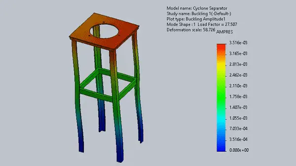
In the second case, we simulate the Cyclone Separator stand with metallic stiffener and going to change the position of stiffener accordingly. Also applied load on the top face based on the procedure as discussed in the procedure section. here we are applying force on one side and fixing on another side i.e fixing the legs of cyclone separator stand and applying a force of 150 kilonewtons on the top face and changing the position of stiffener accordingly. to do that we are using a new study defining its various parameters as discussed in the procedure section. after running the simulation we get the final output as shown below.
1. Unit System:

2. Design Study Setup:
i. Design Variables:

ii. Constraints:

iii. Goals:

iv. Output:
after running the simulation we get the final output as shown below.
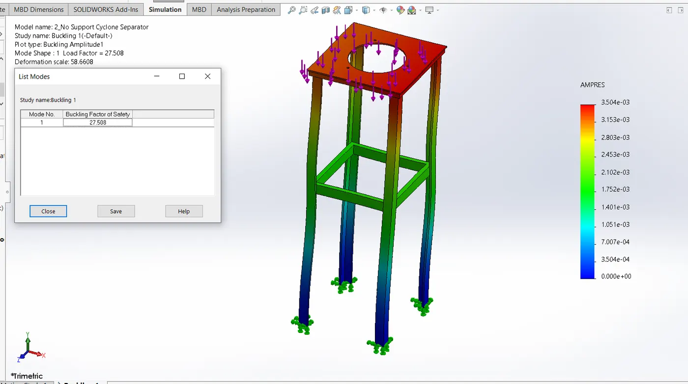
Where:-
The maximum buckling amplitude is indicated in red while the minimum buckling amplitude is indicated as a blue. the green area indicates the average buckling amplitude.
Also, the change in the position of the stiffener with steps provided (Automatically) During Simulation can be visualized from the following animation.
5. Result and Conclusion:-
5.1 Cyclone Separator stand without metallic stiffener:
In the case of cyclone separator stand without metallic stiffener we can see that from the simulation data and simulation image the buckling factor of safety calculated is 9.3496,
| Study name : Buckling 1 | |
| Mode No. | Buckling Factor of Safety |
| 1 | 9.3496 |
it is acceptable because in engineering the factor safety two and three times is enough for the consideration (based on application). but we can further improve the buckling factor of safety by adding a metallic stiffener.
5.2 Cyclone Separator stand with metallic stiffener:
In the case of cyclone separator stand with metallic stiffener we can see that from the simulation data the buckling factor of safety calculated is varying as the position of the stiffener changes.
We have a design study in which FOS is greater than 25 (as defined in the constraints) but out of we have to max the buckling FOS (i.e Defined in the goals). Now we will find the best value based on the constraints and goals provided.
The data calculated is as below with respect to the positions of the stiffener.
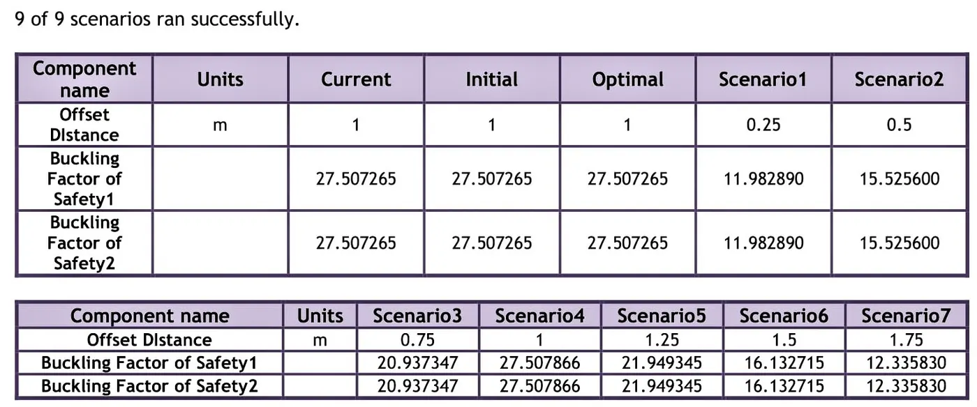
Here we can see that as the stiffener changes its position the buckling factor of safety is changes accordingly. i.e the buckling factor of safety is minimum at the starting and end of the stiffener which indicates that non-economical design. But when the stiffener holds the position of 1 meter from the top face the bucking factor of safety in higher which is an economical position for a stiffener.
this caused because at this position the Deformation Scale in minimum while satisfying all the defined parameters.

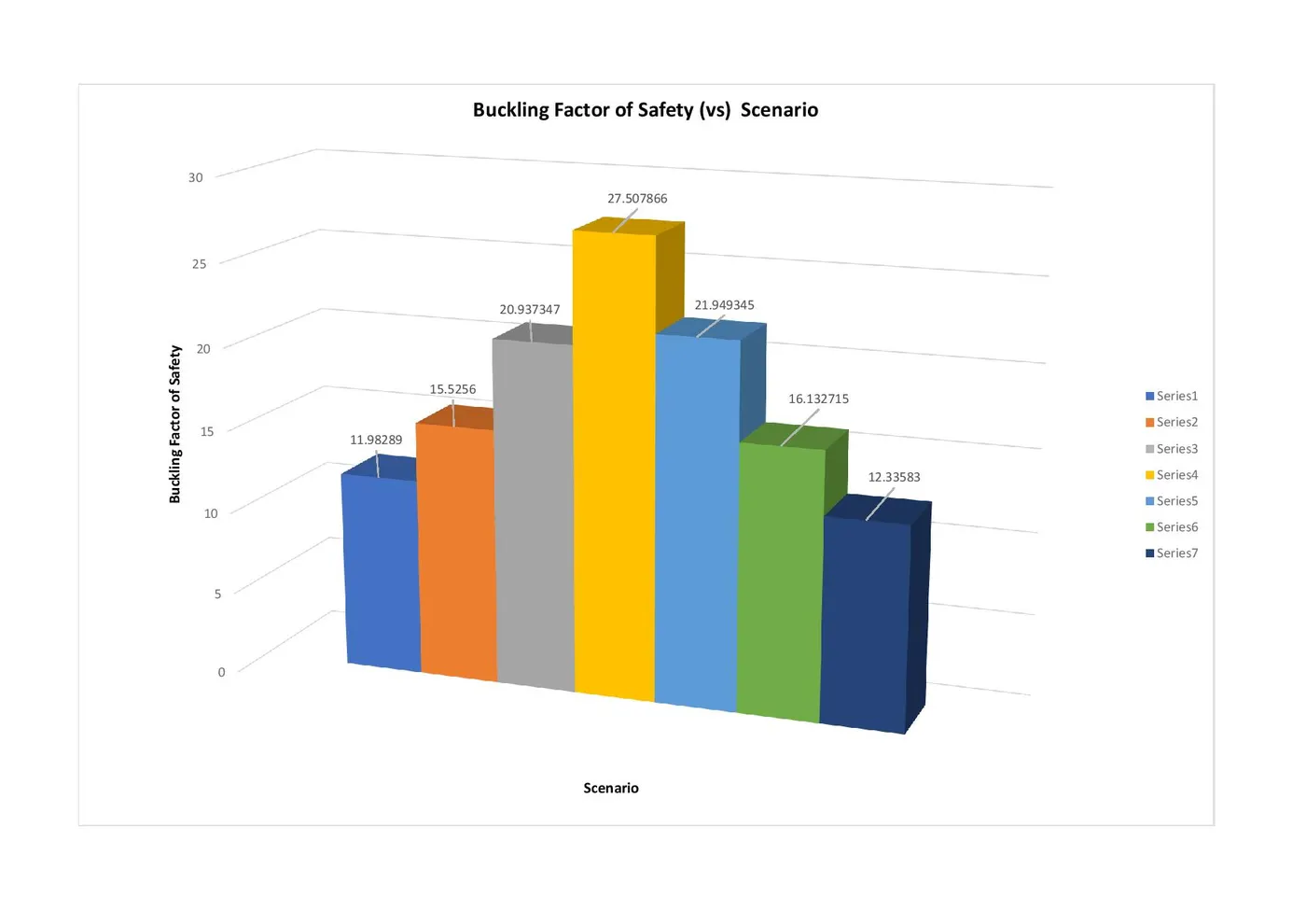
From all the scenarios the Optimum position in cyclone separator stand with metallic stiffener is calculated as 1 meter offset from the top face of the stand having 27.507265 buckling factor of safety as shown below.
5.3 Conclusion:-
In the case of cyclone separator stand without a metallic stiffener we can see that the Deformation scale indicates that the more buckling as compare to the case of cyclone separator stand with a metallic stiffener. Hence the factor of safety is less in the first case and chances of failure are more. While the case 2 i.e stiffener provide more rigid support and reduce the buckling.
Hence, By comparing the first case and second case that is cyclone separator stand without a metallic stiffener and cyclone separator stand with a metallic stiffener we can conclude that, adding stiffener at a calculated optimum location increases the buckling factor of the safety of the structure.
Reference:-
Standard Textbook:- Strength of Material by R.S. Khurmi.
https://en.wikipedia.org/wiki/Buckling
The Flow of Report:-
1. Objective.
2. Basics.
3. Procedure.
4. Simulation and Analysis.
5. Results and Conclusion.