Analysis & Design of RCC shear walls in the model using ETABS
Aim
Challenge deals specifically with the shear wall of size 300x1500 at grid A-11 in the structural model.
And provide the specificied longitudinal reinforcement and Shear reinforcement as per IS 13920.
First we have to analyse the model which is given in the attachment file
Before analysis we have to check the model
As we have to design the shear wall at the grade A-11
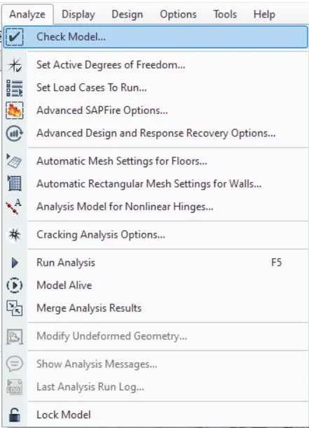
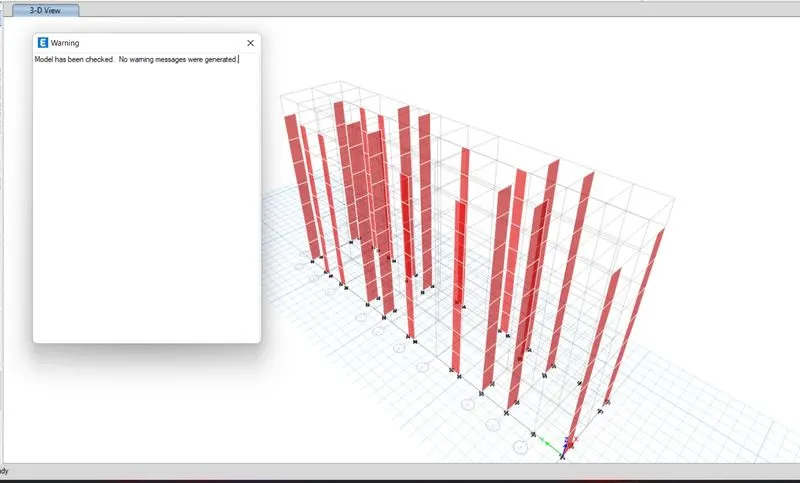
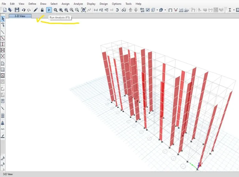
Now click on the shear wall design toolbar
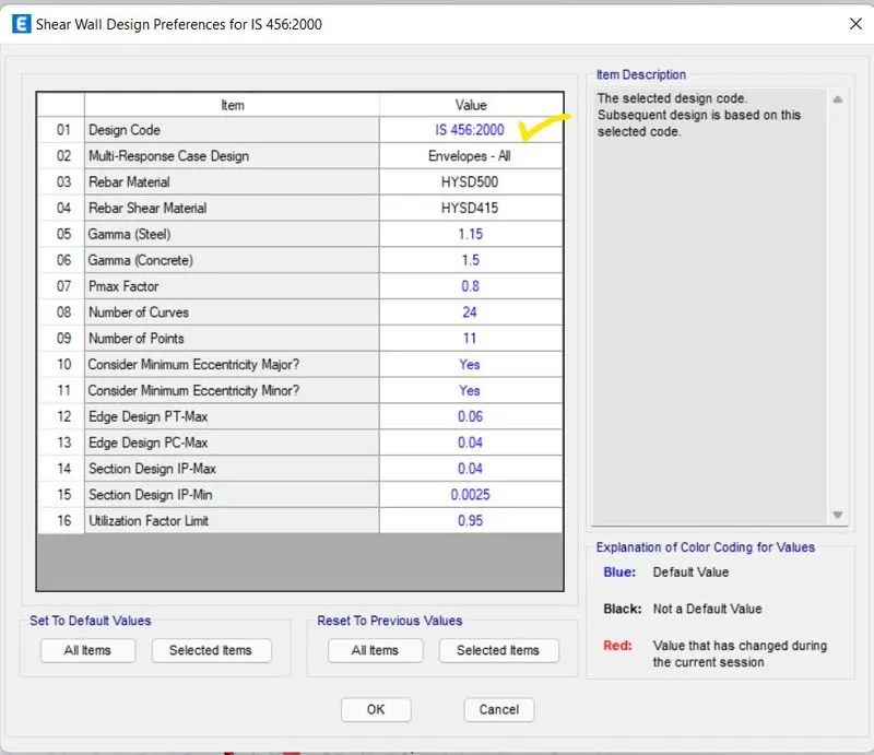
Check the design preference
And click on design option
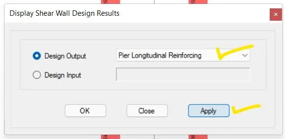
Now for displaying the pier reinforcement ratio
Click on design info and pier reinforcement ratio
- Manual calculation as per IS code
Overall height Of wall h=21m,
Length Of wall L 1500mm
Ratio =(h/L) = 21000/1500 = 14 >2
Diameter than can be used in RC wall should not exceed 1/10th of thickness of wall. as per IS code
So 300/10 = 30mm
25mm dia rebar is used in the detailing
The maximum spacing Of longitudinal / transverse rebar should not exceed as per IS code
(i) 115th Of horizontal 2300mm
(ii) 3 times of thickness (t) 3 x 300 = 900mm
(iii) 450mm
maximum 300mm spacing
Minimum horizontal reinforcement calculation IS-13920-2016
2 (Ph — 0.0025)
= 0.01672 Of cross section Of RC wall
= 1500 x 300 x 0.01672 = 7524 sq.m
=7524 / 21
=358 sq.m
16mm dia at 100 mm c/c spacing which Will give = 1000/100 x 2 x 201 4020 sq. mm
Minimum boundary reinforcement calculation IS-13920-2016
= 0.008 x 300 x 300 = no sq.mm
8 numbers 12mm dia rebar • B x 113 • 904 sq.mm
Minimum web reinforcement calculation as per Table-I of IS13920-2016
 *0.0025
=0.0025 x 900 x 300 -675 sq-mm
8 numbers 12mm dia rebar 8 x 113 904 sq.mm
Overall RC Wall Vertical reinforcement
 0.0025 + 0.01375
= 0.00525 x 1500 x 300 = 2363 sq.mm
24 numbers 12mm dia rebar • 24 x 113 2712 sq.mm
Boundary element special confining reinforcement
maximum spacing of confinement is 100mm as per drawing as per Clause 10.44 of IS13920
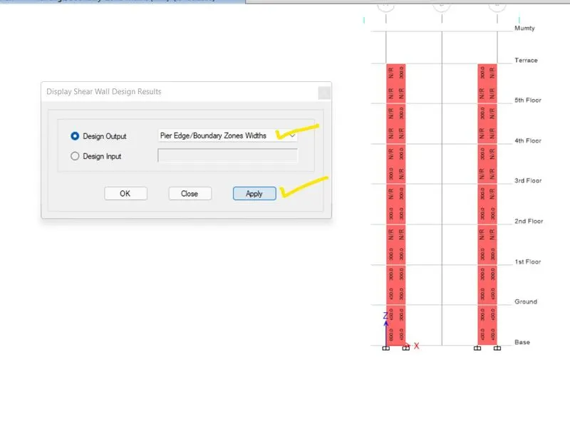
Below image shows the Boundary element value

- Provide elevation drawings of the reinforcement details of the shear wall from base up to terrace.
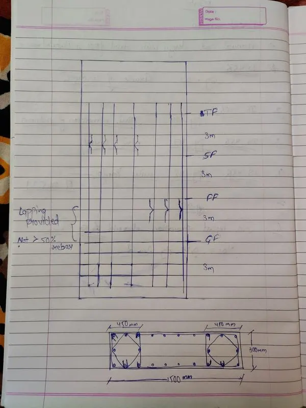
For the 3rd floor the arrangment changes from the 450mm to the 300mm for the corner reinforcement area.
Result
We have design the shear wall and detailed it as per IS-13920 and verified it with software result.
Provide elevation drawings of the reinforcement details of the shear wall from base up to terrace.
Provide extract values of longitudinal steel ratio, boundary element length and shear reinforcing ratio from the design results.