Analysis & Design of RCC shear walls in the model using ETABS
AIM:
To analyse and design of RCC shear walls in the model,
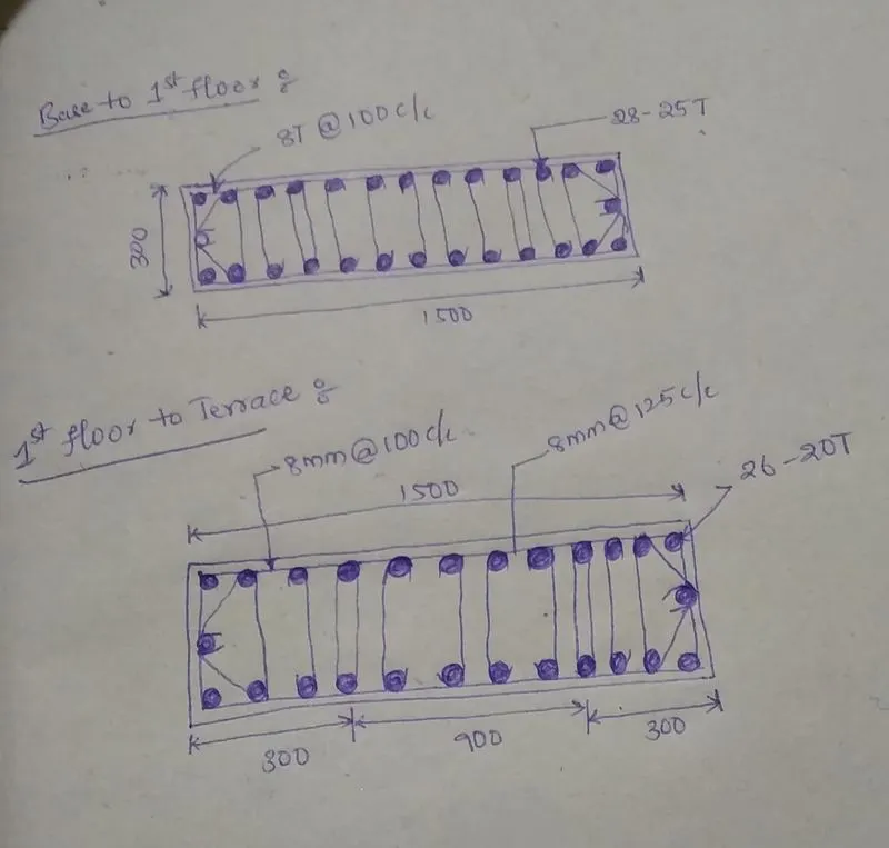
To provide the cross secctional steel arrangement of the shear wall from base to terrace level by using IS 13920-2016.
The drawings of the reinforcement details of the shear wall from the base up to terrace.
Introduction:
Shear walls are vertical elements of the horizontal force resisting system.
They are constructed to counter the effects of lateral load acting on a structure.
When shear walls are designed and constructed properly, and they will have the strength and stiffness to resist the horizontal forces.
Shear walls are especially important in high- rise buildings subjected to lateral wind and seismic forces.
Shear walls are not only designed to resist gravity / vertical loads, but they are also designed for lateral loads of earthquakes / wind.
Procedure:
- first open the etab file which is attached to this challenge
- next put the model in 3D view
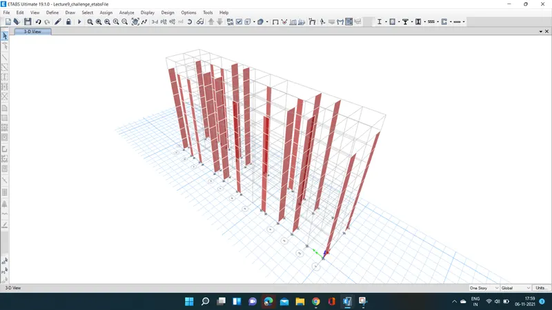
- next from the display tab we select the option " show tables"
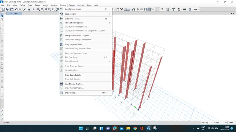
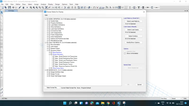
- after selecting the show table option the new tab is visible
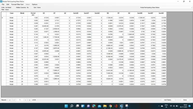
- now select modal participation mass ratio and click on the OK button
- then modal participating mass ratio will be visible
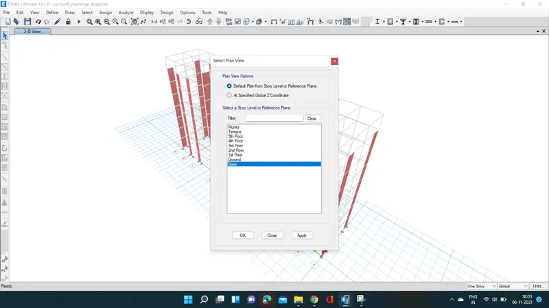
- next open the select plan view tab and select the base floor
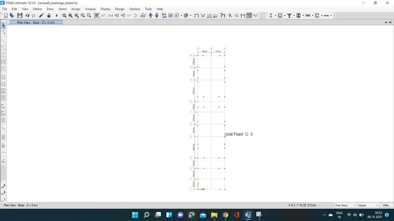
- the base floor plan will be visible
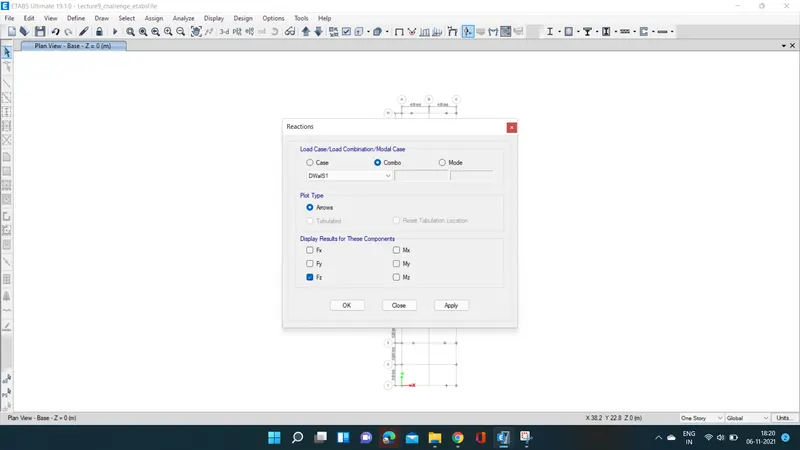
- we open the reation tab then we select the earthquake laod towards x direction (EQX) in the load case, then click on the ok button
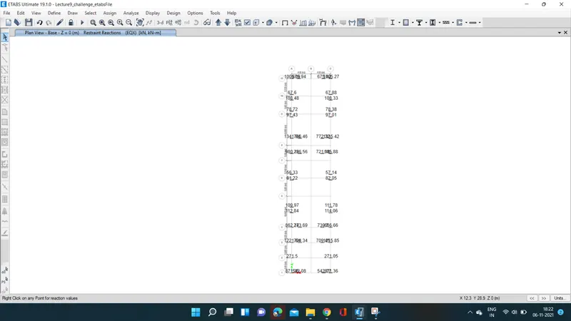
- now the base shear reaction will appear
- when we divide the base shear taken up by the shear wall divided by the total base shear of the building will get the % of the shear forces taken up b the shear wall.
- if that is less than 80% that is more shear wall is required
- next from the display option we select the show tables option
- after selecting the show table option, new tab will be opened
- then select the base reactions and click on the ok button
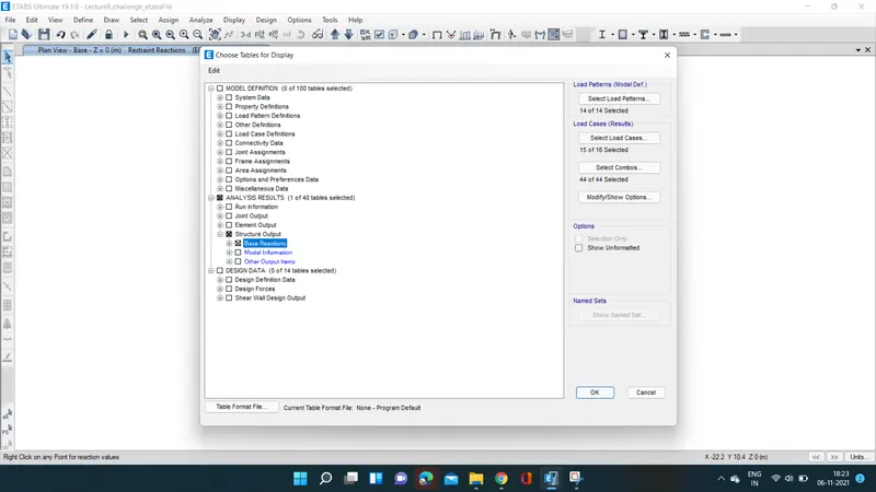
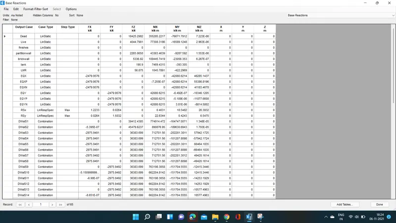
- the base reaction table will be visible
- in the below table, the total base shear of EQX and EQY will be taken for the calculating the % of tthe shear force taken up by the shear wall.
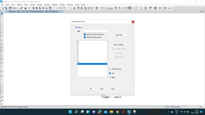
- next open the select elevation view tab and select the 11
- next the election view of grid A- 11 will be visible
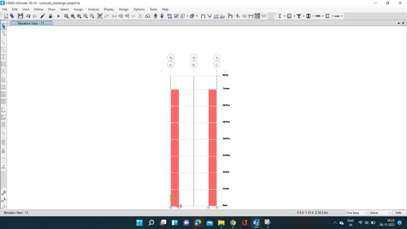
- next we have to start the design by selecting the start design/ check option
- now we have to wait till the design completes that will take a few seconds to complete the design 2
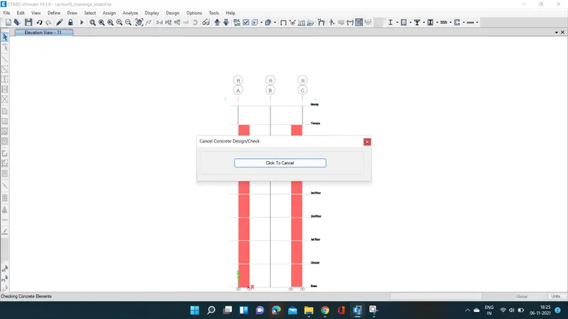
- we need to select the display design info option and then select pier reinforcement ratios in the design output and click on the ok button
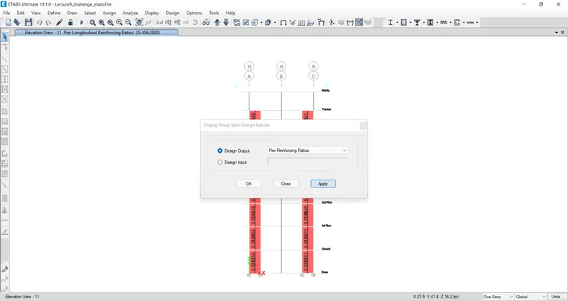
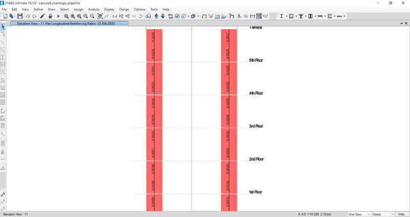
- now the pier reinforcement ratios will be visible
- we again select the display design info option and select pier shear reinforcement in the design output and click ok
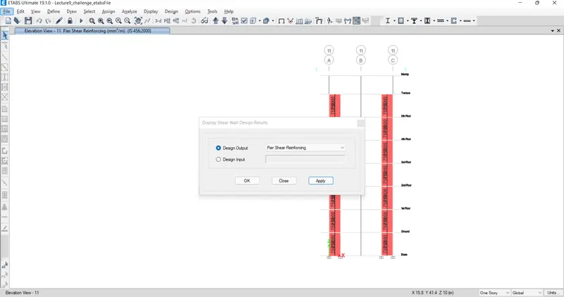
- now the pier shear reinforcement details will be visible
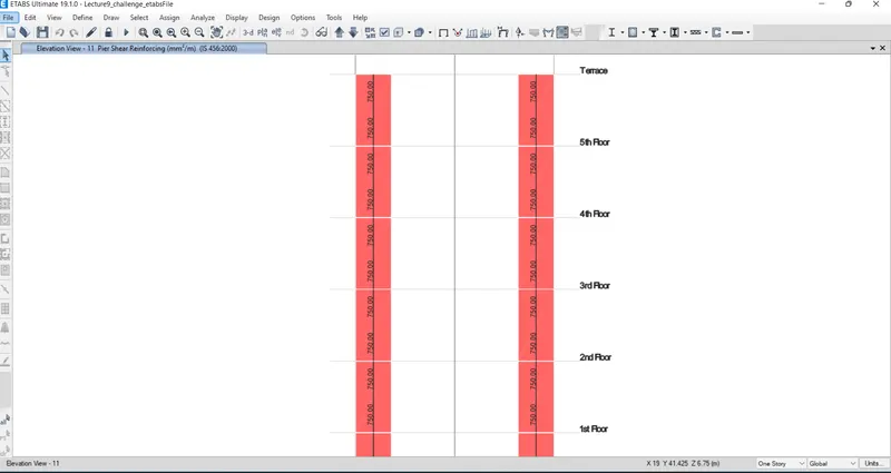
- select display design info option and select pier edges/boundary zones widths in the design output and click on the ok button
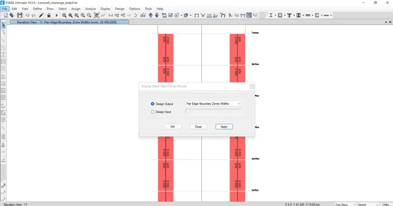
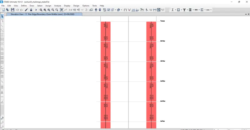
- the details of the boundary elements will be visible
- next right click on the shear wall the design deatils of shear wall will be visible
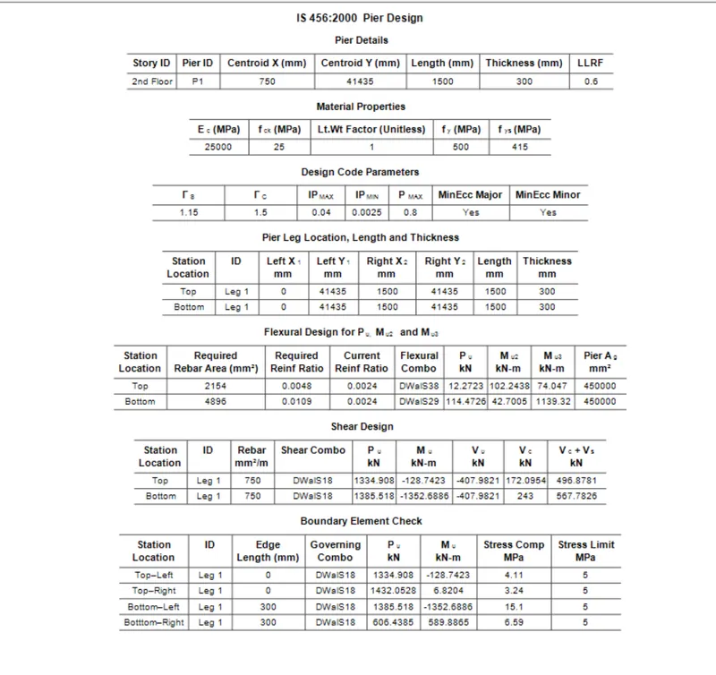
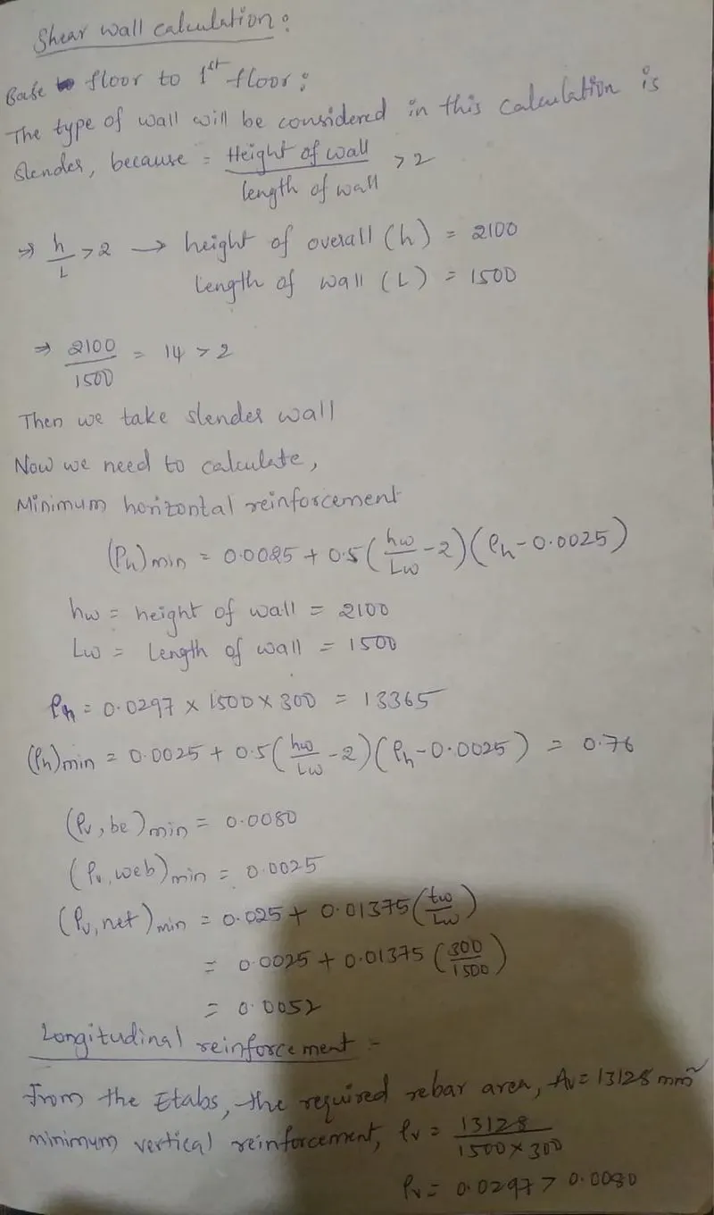
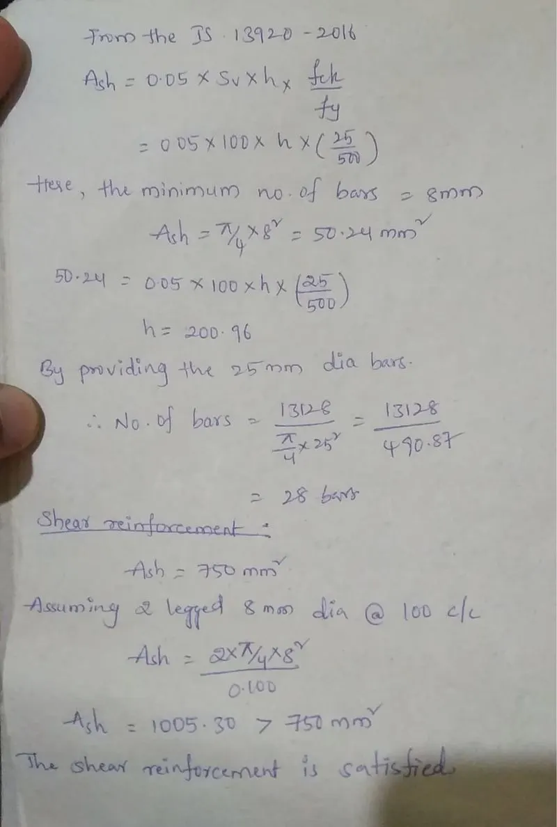
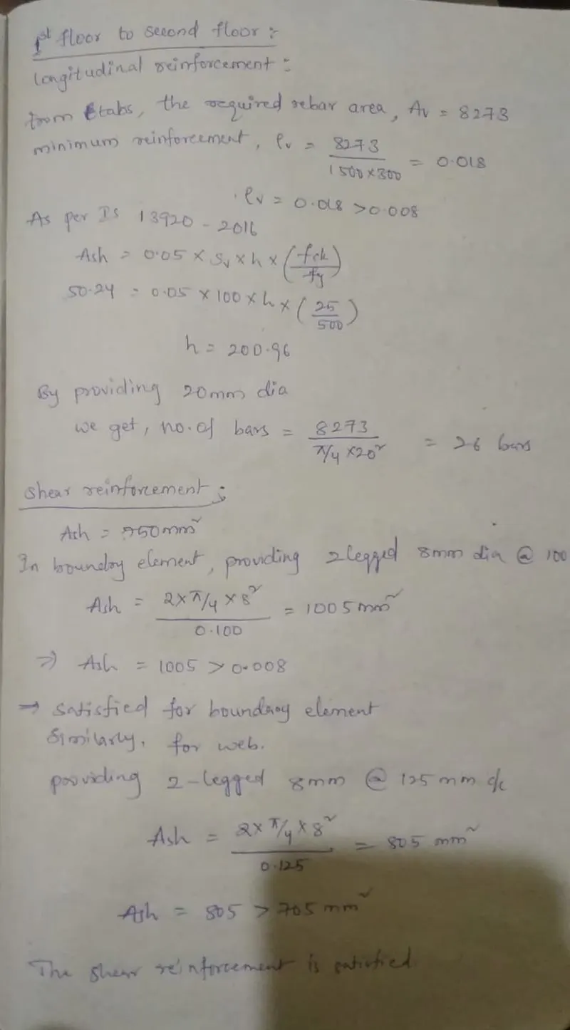
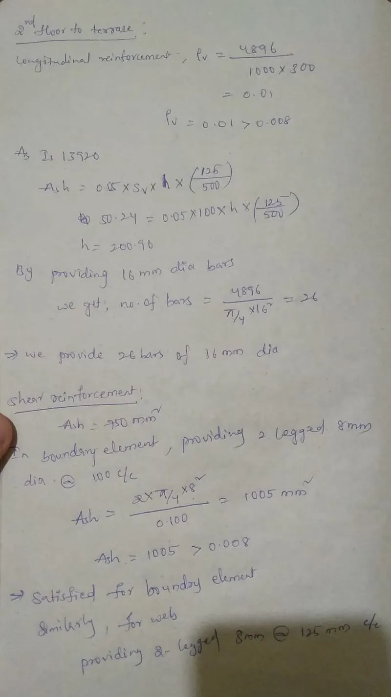
Now we calculate shear wall from base to terrace

conclusion:
Provided the cross sectional steel arrangement of the shear wall from its base up to terrace, in compliance with provisions of IS 13920 – 2016.
Hence Analysis & Design of RCC shear walls in the model using ETABS is done.