Analysis & Design of RCC shear walls in the model using ETABS
AIM:
- To Extract values of longitudinal steel ratio, boundary element length and shear reinforcing ratio from the design results.
- To tProvide cross sectional steel arrangement of the shear wall from its base up to terrace.
- Using AutoCAD application for this exercise or Alternatively, it can be drawn by hand as well.
- To provide elevation drawings of the reinforcement details of the shear wall from base up to terrace.
INTRODUCTION:
- Shear walls are vertical elements of the horizontal force resisting system.
- They are constructed to counter the effects of lateral load acting on a structure.
- When shear walls are designed and constructed properly, and they will have the strength and stiffness to resist the horizontal forces.
- Shear walls are especially important in high-rise buildings subjected to lateral wind and seismic forces.
PROCEDURE:
- Open Challenge and download the attached file
- open it in the etabs 2018.
- Go to tool ribbon select analyze < run analysis.
- From tool bar select Display < show table option, the following screen will appear.
- Next, go to open the reactions tab,
- then select the eartquake load towards X-direction (EQX) in the load case,
- then click < apply < ok
- Now the base shear reactions will appear, as shown below.
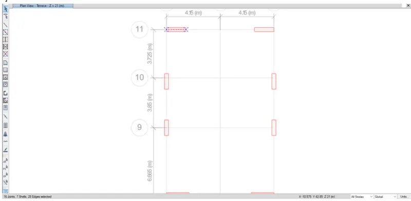
-
- When we divide the base shear taken up by the shear wall divided by the total base shear of building will get the percentage of the shear forces taken up by the shear wall.
- And if that is less than 80%, that means more shear wall is required in the frame to resist shear.
- After selecting the show tables option the new tab will be visible.
- Now, select the Base Reactions < ok
- Next the Base Reactions table will be visible, as shown.
- In the below table, the total base shear of EQX and EQY will be taken for the calculating percent of shear forces taken up by the shear wall
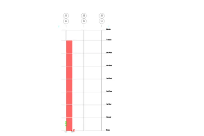
- After the selection of the shear walls and checing the necessary data we are going to run the analysis.
- After the analysis we ge the report of the model.
- After the reinforcing details we are begining with teh specification and guidelines check on the design of the shear wall.
- After this the model is taken to shear wall design.
- The shear wall design is shown below.
- Which shows the pier longitudinal reinforcing
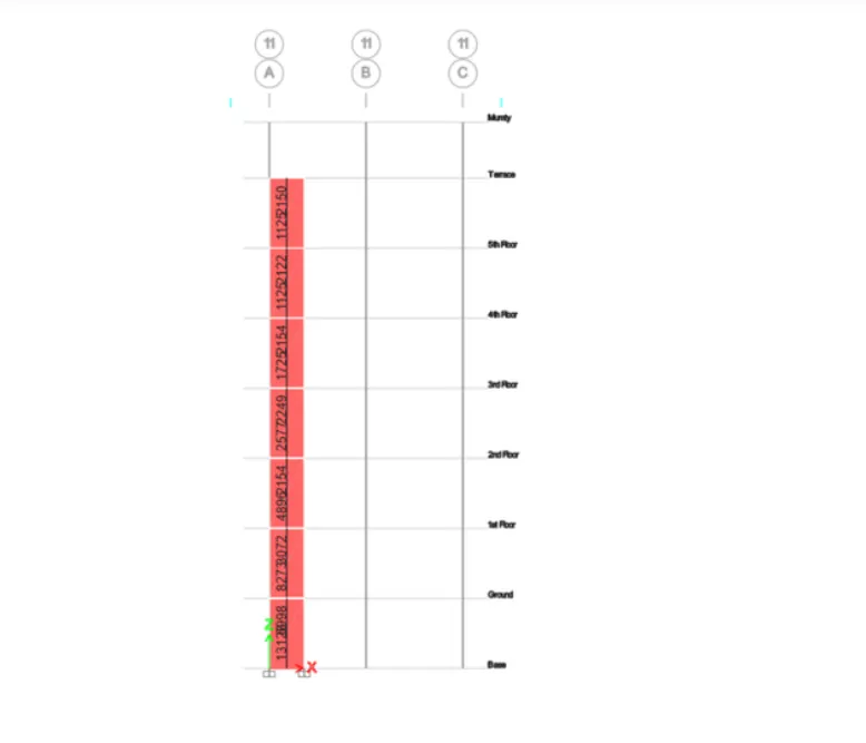
- Classification of shear wall as per IS 13920-2016 Clause 10.1.4
Slender wall
hw / Lw = 21000/1500 = 14>2
- Min. net vertical reinforcement as per IS 13920-2016 Table-1
= 0.0025+0.01375(300/1500) which we multiply with the top view of the wall as it is vertical reinforcement we get
= 2363mm^2
- Min. Vertical reinforcement within boundary element table-1
1440mm^2 on left (600mm width boundary element)
1080mm^2 on right(450mm width boundary element)
- Minimum horizontal reinforcement in shear wall per IS 13920-2016 Table 1
(ρh)min = 0.0025 + 0.5((hw/Lw)-2) (ρh – 0.025)
ρh = 750/(300*1000) = 0.0025
hw = 21000
Lw = 1500
(ρh)min = 0.0025 + 0.5 (21/15 – 2) *0
(ρh)min = 0.0025 which is the same 750 mm2/m
- Max dia of the rebar for shear wall as per IS 13920-2016 Clause 10.1.8
1/10th of wall thickness = 300/10 = 30mm
where commercial rebar dia used to be 25mm which can be adopted
- Confining reinforcement spacing for boundary elements as per IS 13920-2016 Clause 10.4.4
- 1/3 of min member dimension = 300/3 =100mm
- 6 times smalles main rebar = 6*25=150mm
- 150mm permissible if vertical bars are spaced at maximum 200mm
max spacing of confining reinforcement in boundary element 150mm
- Confining reinforcement within boundary element as per IS 13920-2016 Clause 10.4.4
Ash = 0.05 Sv h fck/fy
Sv = 150mm, h= 1000mm
Ash = 452mm2
- With the above procedure we are detaining the reinforcement of the shear wall.
- The drafting is done in autocad and is shown below
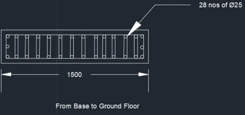
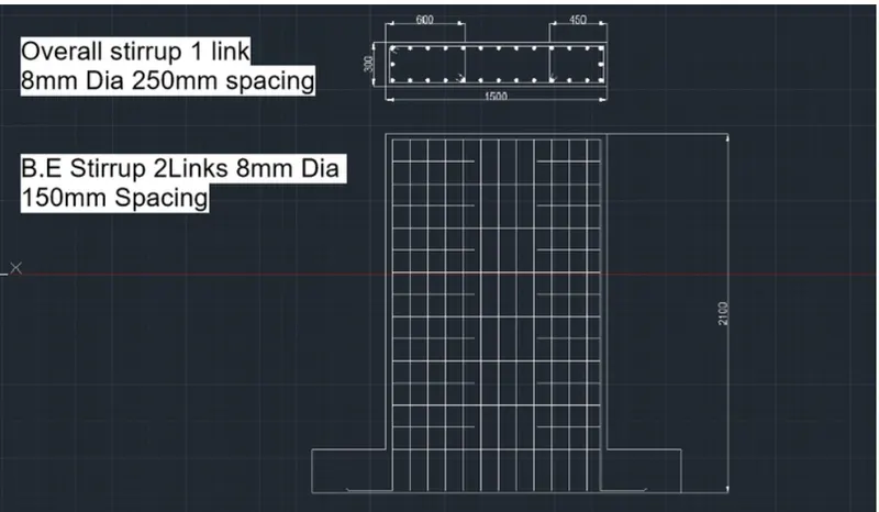
Result:
- The model was inserted.
- Resolutions was derived.
- Required design details of teh shear wall was shown
- The required details and drawing were shown
- Provided cross sectional steel arrangement of the shear wall from its base up to terrace, in compliance with provisions of IS 13920 – 2016.
- Designed the RCC shear wall using the design results from ETABS file.
- Provide elevation drawings of the reinforcement details of the shear wall from base up to terrace.