Analysis & Design of RCC shear walls in the model using ETABS
Ans:
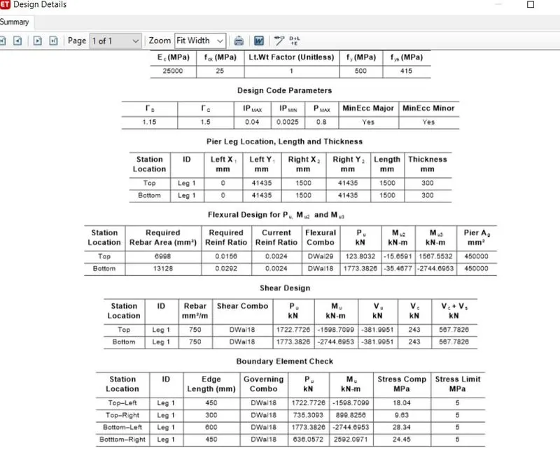
Aim:-To provide the exact values of longitudinal steel ratio, boundary element length and shear reinforcing ratio from the design results.
To provide c/s steel arrangements of shear wall from its base upto terrace ,as per IS 13290-2016
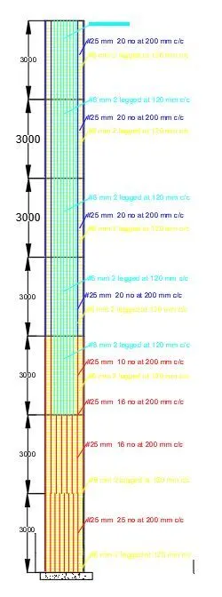
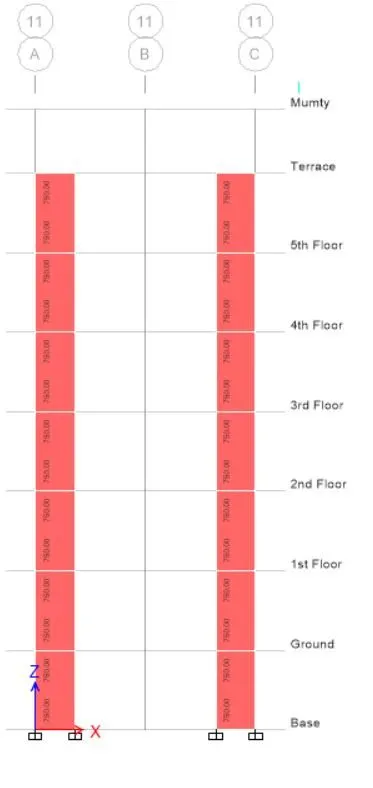
To provide elevation drawings of the reinforcement details of the shear wall from base upto terrace.
Procedure: -
1.Shear walls are vertical elements of the horizontal force resisting system
- They are constructed to counter the effect of lateral load acting on a structure.
3.When the shear walls are designed and constructed properly, they will have strength and stiffness to resist the horizontal forces.
4.Shear walls are highly imported in the high rise buildings which are subjected to wind and seismic forces.
Steps;-
- In the first step open the given Etabs file and click on the run the analysis option.
- Once the analysis is done completely.
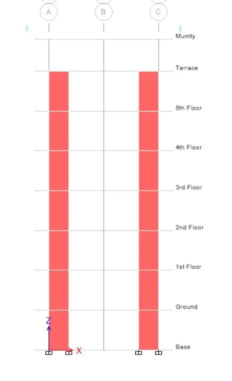
- In the next step go to shear wall design and select start design/check the structure.
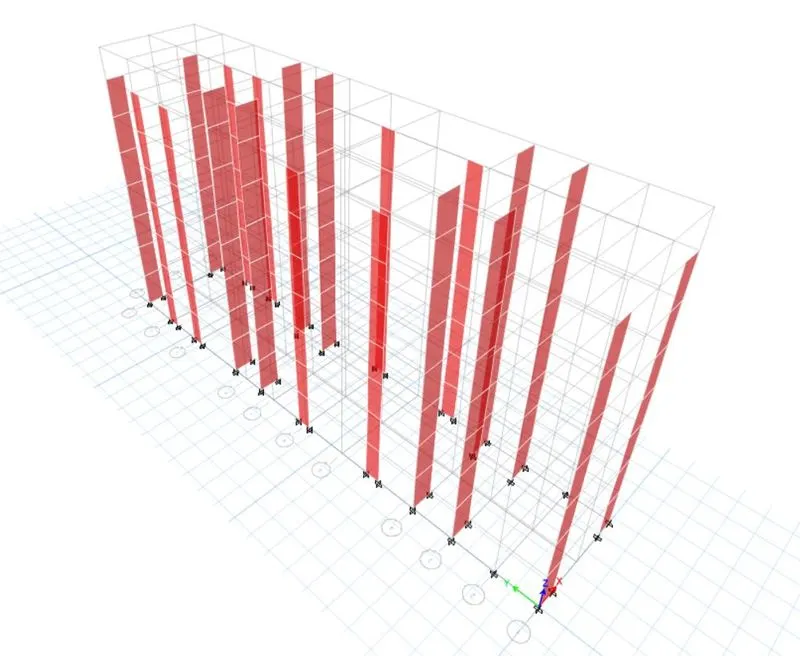
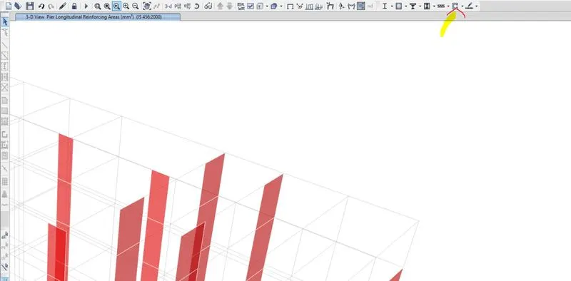
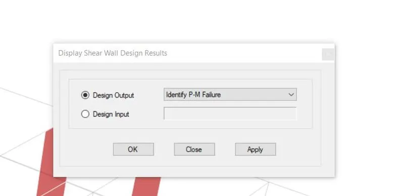
- In the next step go to shear wall design and select display design info.
- Select the p-m failure.
- We can observe that there are no failures in the A-11 grid shear wall.
- Select the shear failure.
- We can observe that there are no failures in the A-11 grid shear wall.
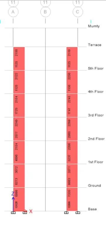
- In the next step click display design info and select the longitudinal pier reinforcing.
|
Longitudinal pier Reinforcing of the Grid A 11 |
|||
|
Sl.no |
Storeys |
Top |
Bottom |
|
1 |
Base |
6998 |
13128 |
|
2 |
Ground |
3072 |
8273 |
|
3 |
First |
2154 |
4896 |
|
4 |
second |
2249 |
2577 |
|
5 |
Thired |
2154 |
1725 |
|
6 |
Fourth |
2122 |
1125 |
|
7 |
Fifth |
2150 |
1125 |
- In the next step click on the longitudinal pier steel ration the value for the A11 grid is as follow
|
Longitudinal pier Reinforcing Steel Ratip of the Grid A 11 |
||||
|
Sl.no |
Storeys |
Top |
Bottom |
|
|
1 |
Base |
0.0156 |
0.0292 |
|
|
2 |
Ground |
0.0068 |
0.0184 |
|
|
3 |
First |
0.0048 |
0.0109 |
|
|
4 |
second |
0.005 |
0.0057 |
|
|
5 |
Thired |
0.0048 |
0.0038 |
|
|
6 |
Fourth |
0.0047 |
0.0025 |
|
|
7 |
Fifth |
0.0048 |
0.0025 |
|
- As per clause number 1.1. of Is 13290 2016 the minimum thickness of the wall should not be less than 150 mm or 300 mm in case of shear walls. So in the question its being given that the thickness of shear wall is 300 mm hence it is safe.
- As per clause number 1.2. of Is 13290 2016 the minimum ratio of length of the wall to its shall be equal to 4.
=1500/300
=5 >4 hence ok.
- As per clause number 1.3. of Is 13290 2016
Height of the wall=21m, length of the wall=1.5 m
hw/lw=21/1.5=14 hence the wall is slender wall.
|
Longitudinal pier Reinforcing Steel Ratip of the Grid A 11 |
|||
|
Sl.no |
Storeys |
Top |
Bottom |
|
1 |
Base |
0.0156 |
0.0292 |
|
2 |
Ground |
0.0068 |
0.0184 |
|
3 |
First |
0.0048 |
0.0109 |
|
4 |
second |
0.005 |
0.0057 |
|
5 |
Thired |
0.0048 |
0.0038 |
|
6 |
Fourth |
0.0047 |
0.0025 |
|
7 |
Fifth |
0.0048 |
0.0025 |
All these above values are less than 4%. Hence the shear wall is safe.
- In the next step go to shear wall design icon and click on display design info and select boundary element.
|
Boundry elements length of the Grid A 11 |
EDGE length in mm |
||||
|
Sl.No |
|
Top-Left |
Top -Right |
Bottom-left |
Bottom-Right |
|
1 |
Foundation to base |
450 |
300 |
600 |
450 |
|
2 |
Base to GF |
300 |
300 |
450 |
300 |
|
3 |
GF to 1st Floor |
0 |
0 |
300 |
300 |
|
4 |
1st to 2nd |
0 |
300 |
300 |
300 |
|
5 |
2nd to 3rd |
0 |
300 |
300 |
0 |
|
6 |
3rd to 4th |
0 |
300 |
0 |
0 |
|
7 |
4th to 5th |
0 |
300 |
0 |
0 |
- Minimum Reinforcement in shear walls calculation as per Table 1. Of IS 13290-2016.
iii.Slender walls
Lw=1500 mm,tw=300 mm hw=21000 mm
(ρh )min=0.0025+0.5((hw/Lw)-2)( ρh -0.0025)
=0.0025+0.5((21000/1500)-2)(0.0292-0.0025)
=0.1627
(ρv,be)min=0.0080
(ρv,wee)min=0.0025
((ρv,net)min=0.0025+0.01375(tw/Lw)
=0.0025+0.01375(300/1500)
=5.25*10^-3
- As per the 10.1.7 of Is 13290-2016 ,Rinforcement bars shall be provided two curtains within the c/s of the wall ,with each curtain having bars running along vertical and horizontal directions when.
- Factored shear stress demand in the wall exceeds 0.25sqrt fck
- Or Wall thick ness is 200 mm or higher
In our case the all the stress are above 5. And wall thickness provided is 300 mm .
|
Boundry elements length of the Grid A 11 |
EDGE length in mm |
||||
|
Sl.No |
|
Top-Left |
Top -Right |
Bottom-left |
Bottom-Right |
|
1 |
Foundation to base |
450 |
300 |
600 |
450 |
|
2 |
Base to GF |
300 |
300 |
450 |
300 |
|
3 |
GF to 1st Floor |
0 |
0 |
300 |
300 |
|
4 |
1st to 2nd |
0 |
300 |
300 |
300 |
|
5 |
2nd to 3rd |
0 |
300 |
300 |
0 |
|
6 |
3rd to 4th |
0 |
300 |
0 |
0 |
|
7 |
4th to 5th |
0 |
300 |
0 |
0 |
- As per 10.4.1. of IS 13290-2016 Boundry elements will be provided along the vertical boundaries of walls ,when the extreme fibre compressive stress in the walls exceeds.
In Grid A11 the shear wall at the base level if we check all the values of compressive stress are exceeding 0.2fck=0.2*25=5N/mm^2.
- So since we require boundry elements in the Shear wall at the base
The special confining reinforcement as per 10.4.4.4 of IS 13290-2016 is
Ash=0.05 Sv h fck/fy
There fore using 8mm dia bars
Ash=22/7*8*8*0.25
=50.26 mm^2
fck=25,fy=500
Ash=0.05 Sv h fck/fy
50.26=0.05*100*h*25/500
Sv=201.0mm
| Longitudinal pier Reinforcing of the Grid A 11 | ||||
| 1 | Base to Ground floor level | |||
| Height of the shear wall | 21000 | mm | ||
| Thickness of the wall | 300 | mm | ||
| length of the wall | 1500 | mm | ||
| fck Mpa | 25 | Mpa | ||
| fy | 500 | Mpa | ||
| Sv | 100 | mm | ||
| Boundry elements length from Etabs | ||||
| Top-Left | Top -Right | Bottom-left | Bottom-Right | |
| 450 | 300 | 600 | 450 | |
| Boundry element length to be provided on either end is | 600 | mm | ||
| So the web length will be left with | 300 | mm | ||
| which is nothing there fore on the entire length the reinforcement of boundry element is provided. | ||||
| Type of wall As per 10.1.4 of IS 13290-2016 | ||||
| hw/lw | 14 | |||
| Slender wall | ||||
| Boundary element Calculation | ||||
| Asper Table 1 of IS 13290-2016 | ||||
| vertical reinforcemment in BE is (ρ v min) for | 0.0008 | |||
| Minimum Area of Reinforcement | 360 | mm^2 | ||
| Longitudinal Reinforcment required | ||||
| Area of Rebar required from the etabs | Av | 13128 | (mm^2) | |
| Dia of bars used in mm | 25 | |||
| Area of one rebar | Av | 490.9375 | (mm^2) | |
| Number of bars required | No.s | 26.74067473 | ||
| Spacing of the bars | ||||
| Ash=0.05 Sv h fck/fy | ||||
| Dia of Shear reinforcemebt bars | mm | 8 | ||
| Area of one rebar | Av(mm^2) | 50.272 | ||
| h=Ash*fy/0.05 Sv fck | mm | 201.088 | ||
| As per 10.1.8 of Is 13290 2016 the largest dia used in longitudinbal bars 1/10th of thickness of that | ||||
| a) | Thickness used | mm | 300 | |
| 1/10th of thickness | mm | 30 | ||
| dia of bars used | mm | 13128 | ||
| FALSE | ||||
| As per 10.1.9 of Is 13290 2016maximum spacing of vertical/horizontal reinforcement should be smaller of | ||||
| a)1/5th of horizontal length | mm | 300 | ||
| b)3 times the thickness tw of web | mm | 900 | ||
| c) 450 mm | mm | 450 | ||
| provided spacing | mm | 200 | ||
| hence 26 numbers 25 mm dia bars are provided at 120mm c/c | ||||
| Shear Reinforcment required | ||||
| Ash from Etabs | mm^2 | 750 | ||
| As per 10.4.4 of IS 13290-2016 | ||||
| The spacing between the reinforcement in the special confining zone shall not be lesser of | ||||
| a)1/3rd of minimum dimension of BE | 0 | mm | ||
| b)6times the longitudinal dia bars | 0 | mm | ||
| c)100 mm | 100 | mm | ||
| Values from etabs | ||||
| Minimum Spacing | 0 | mm | ||
| 100 | mm | |||
| There fore spacing provided in the confining zone of Boundry element in mm | ||||
| Ashear reinforcement from Etabs | mm^2 | 750 | ||
| Dia of Shear reinforcemebt bars | mm | 8 | ||
| Area of one rebar | Av(mm^2) | 50.272 | ||
| Number of bars | 7.459420751 | |||
| Nos. | 8 | |||
| There fore 8 mm dia 2 legged shear reinforcemeint is provided at 100 mm c/c in entire region. | ||||
| 2 | GF level to 1st floor | |||
| Height of the shear wall | 21000 | mm | ||
| Thickness of the wall | 300 | mm | ||
| length of the wall | 1500 | mm | ||
| fck Mpa | 25 | Mpa | ||
| fy | 500 | Mpa | ||
| Sv | 100 | mm | ||
| Boundry elements length from Etabs | ||||
| Top-Left | Top -Right | Bottom-left | Bottom-Right | |
| 300 | 300 | 450 | 300 | |
| Boundry element length to be provided on either end is | 450 | mm | ||
| So the web length will be left with | 600 | mm | ||
| which is nothing there fore on the entire length the reinforcement of boundry element is provided. | ||||
| Type of wall As per 10.1.4 of IS 13290-2016 | ||||
| hw/lw | 14 | |||
| Slender wall | ||||
| Boundary element Calculation | ||||
| Asper Table 1 of IS 13290-2016 | ||||
| vertical reinforcemment in BE is (ρ v min) for | 0.0008 | |||
| Minimum Area of Reinforcement | 360 | mm^2 | ||
| Longitudinal Reinforcment required | ||||
| Area of Rebar required from the etabs | Av | 8273 | (mm^2) | |
| Dia of bars used in mm | 25 | |||
| Area of one rebar | Av | 490.9375 | (mm^2) | |
| Number of bars required | No.s | 16.85143221 | ||
| Spacing of the bars | ||||
| Ash=0.05 Sv h fck/fy | ||||
| Dia of Shear reinforcemebt bars | mm | 8 | ||
| Area of one rebar | Av(mm^2) | 50.272 | ||
| h=Ash*fy/0.05 Sv fck | mm | 201.088 | ||
| As per 10.1.8 of Is 13290 2016 the largest dia used in longitudinbal bars 1/10th of thickness of that | ||||
| a) | Thickness used | mm | 300 | |
| 1/10th of thickness | mm | 30 | ||
| dia of bars used | mm | 25 | ||
| Clause 10.1.8 is satisfied | ||||
| As per 10.1.9 of Is 13290 2016maximum spacing of vertical/horizontal reinforcement should be smaller of | ||||
| a)1/5th of horizontal length | mm | 300 | ||
| b)3 times the thickness tw of web | mm | 900 | ||
| c) 450 mm | mm | 450 | ||
| provided spacing | mm | 200 | ||
| hence 16 numbers 25 mm dia bars are provided at 120mm c/c | ||||
| Shear Reinforcment required | ||||
| Ash from Etabs | mm^2 | 750 | ||
| As per 10.4.4 of IS 13290-2016 | ||||
| The spacing between the reinforcement in the special confining zone shall not be lesser of | ||||
| a)1/3rd of minimum dimension of BE | 99 | mm | ||
| b)6times the longitudinal dia bars | 150 | mm | ||
| c)100 mm | 100 | mm | ||
| Values from etabs | ||||
| Minimum Spacing | 99 | mm | ||
| 100 | mm | |||
| There fore spacing provided in the confining zone of Boundry element in mm | ||||
| Ashear reinforcement from Etabs | mm^2 | 750 | ||
| Dia of Shear reinforcemebt bars | mm | 8 | ||
| Area of one rebar | Av(mm^2) | 50.272 | ||
| Number of bars | 7.459420751 | |||
| Nos. | 8 | |||
| There fore 8 mm dia 2 legged shear reinforcemeint is provided at 100 mm c/c in entire region. | ||||
| 3 | First Floor level to 2nd Floor | |||
| Height of the shear wall | 21000 | mm | ||
| Thickness of the wall | 300 | mm | ||
| length of the wall | 1500 | mm | ||
| fck Mpa | 25 | Mpa | ||
| fy | 500 | Mpa | ||
| Sv | 100 | mm | ||
| Boundry elements length from Etabs | ||||
| Top-Left | Top -Right | Bottom-left | Bottom-Right | |
| 0 | 0 | 300 | 0 | |
| Boundry element length to be provided on either end is | 300 | mm | ||
| So the web length will be left with | 900 | mm | ||
| in this case both boundery elements and web is provided. | ||||
| Type of wall As per 10.1.4 of IS 13290-2016 | ||||
| hw/lw | 14 | |||
| Slender wall | ||||
| Boundary element Calculation | ||||
| Asper Table 1 of IS 13290-2016 | ||||
| vertical reinforcemment in BE is (ρ v min) for | 0.0008 | |||
| Minimum Area of Reinforcement | 360 | mm^2 | ||
| Longitudinal Reinforcment required | ||||
| Area of Rebar required from the etabs | Av | 4896 | (mm^2) | |
| Dia of bars used in mm | 25 | |||
| Area of one rebar | Av | 490.9375 | (mm^2) | |
| Number of bars required | No.s | 9.972756206 | ||
| Spacing of the bars | ||||
| Ash=0.05 Sv h fck/fy | ||||
| Dia of Shear reinforcemebt bars | mm | 8 | ||
| Area of one rebar | Av(mm^2) | 50.272 | ||
| h=Ash*fy/0.05 Sv fck | mm | 201.088 | ||
| As per 10.1.8 of Is 13290 2016 the largest dia used in longitudinbal bars 1/10th of thickness of that | ||||
| a) | Thickness used | mm | 300 | |
| 1/10th of thickness | mm | 30 | ||
| dia of bars used | mm | 25 | ||
| Clause 10.1.8 is satisfied | ||||
| As per 10.1.9 of Is 13290 2016maximum spacing of vertical/horizontal reinforcement should be smaller of | ||||
| a)1/5th of horizontal length | mm | 300 | ||
| b)3 times the thickness tw of web | mm | 900 | ||
| c) 450 mm | mm | 450 | ||
| provided spacing | mm | 200 | ||
| hence 10 numbers 25 mm dia bars are provided at 200mm c/c | ||||
| Shear Reinforcment required | ||||
| Ash from Etabs | mm^2 | 750 | ||
| As per 10.4.4 of IS 13290-2016 | ||||
| The spacing between the reinforcement in the special confining zone shall not be lesser of | ||||
| a)1/3rd of minimum dimension of BE | 0 | mm | ||
| b)6times the longitudinal dia bars | 2945.625 | mm | ||
| c)100 mm | 100 | mm | ||
| Values from etabs | ||||
| Minimum Spacing | 0 | mm | ||
| 100 | mm | |||
| There fore spacing provided in the confining zone of Boundry element in mm | ||||
| Ashear reinforcement from Etabs | mm^2 | 750 | ||
| Dia of Shear reinforcemebt bars | mm | 8 | ||
| Area of one rebar | Av(mm^2) | 50.272 | ||
| Number of bars | 7.459420751 | |||
| Nos. | 8 | |||
| There fore 8 mm dia 2 legged shear reinforcemeint is provided at 100 mm c/c in Boundry element. | ||||
| web region Calculation | ||||
| Asper Table 1 of IS 13290-2016 | ||||
| vertical reinforcemment inweb is (ρ v min) for | 0.0025 | |||
| vertical reinforcemment inweb is (ρ vnet) for | 0.00525 | |||
| Area of vertical reinforcement required | 23.625 | mm^2 | ||
| Using 8 mm 2 legged dia bars | ||||
| dia of bar | mm | 8 | ||
| legged | 2 | |||
| Area of one bar | mm^2 | 100.544 | ||
| Spacing | mm | 125 | ||
| Number of bars | ||||
| Area of shear reinforcment provided | mm^2 | 804.352 | ||
| required | mm^2 | 750 | ||
| Hence ok | ||||
| There fore 8 mm dia 2 legged shear reinforcemeint is provided at 120 mm c/c in Boundry element region. | ||||
| 3 | FF to SF | |||
| Height of the shear wall | 21000 | mm | ||
| Thickness of the wall | 300 | mm | ||
| length of the wall | 1500 | mm | ||
| fck Mpa | 25 | Mpa | ||
| fy | 500 | Mpa | ||
| Sv | 100 | mm | ||
| Boundry elements length from Etabs | ||||
| Top-Left | Top -Right | Bottom-left | Bottom-Right | |
| 0 | 300 | 300 | 300 | |
| Boundry element length to be provided on either end is | 300 | mm | ||
| So the web length will be left with | 900 | mm | ||
| in this case both boundery elements and web is provided. | ||||
| Type of wall As per 10.1.4 of IS 13290-2016 | ||||
| hw/lw | 14 | |||
| Slender wall | ||||
| Boundary element Calculation | ||||
| Asper Table 1 of IS 13290-2016 | ||||
| vertical reinforcemment in BE is (ρ v min) for | 0.0008 | |||
| Minimum Area of Reinforcement | 360 | mm^2 | ||
| Longitudinal Reinforcment required | ||||
| Area of Rebar required from the etabs | Av | 4896 | (mm^2) | |
| Dia of bars used in mm | 25 | |||
| Area of one rebar | Av | 490.9375 | (mm^2) | |
| Number of bars required | No.s | 9.972756206 | ||
| Spacing of the bars | ||||
| Ash=0.05 Sv h fck/fy | ||||
| Dia of Shear reinforcemebt bars | mm | 8 | ||
| Area of one rebar | Av(mm^2) | 50.272 | ||
| h=Ash*fy/0.05 Sv fck | mm | 201.088 | ||
| As per 10.1.8 of Is 13290 2016 the largest dia used in longitudinbal bars 1/10th of thickness of that | ||||
| a) | Thickness used | mm | 300 | |
| 1/10th of thickness | mm | 30 | ||
| dia of bars used | mm | 25 | ||
| Clause 10.1.8 is satisfied | ||||
| As per 10.1.9 of Is 13290 2016maximum spacing of vertical/horizontal reinforcement should be smaller of | ||||
| a)1/5th of horizontal length | mm | 300 | ||
| b)3 times the thickness tw of web | mm | 900 | ||
| c) 450 mm | mm | 450 | ||
| provided spacing | mm | 200 | ||
| hence 10 numbers 25 mm dia bars are provided at 200mm c/c | ||||
| Shear Reinforcment required | ||||
| Ash from Etabs | mm^2 | 750 | ||
| As per 10.4.4 of IS 13290-2016 | ||||
| The spacing between the reinforcement in the special confining zone shall not be lesser of | ||||
| a)1/3rd of minimum dimension of BE | 0 | mm | ||
| b)6times the longitudinal dia bars | 2945.625 | mm | ||
| c)100 mm | 100 | mm | ||
| Values from etabs | ||||
| Minimum Spacing | 0 | mm | ||
| 100 | mm | |||
| There fore spacing provided in the confining zone of Boundry element in mm | ||||
| Ashear reinforcement from Etabs | mm^2 | 750 | ||
| Dia of Shear reinforcemebt bars | mm | 8 | ||
| Area of one rebar | Av(mm^2) | 50.272 | ||
| Number of bars | 7.459420751 | |||
| Nos. | 8 | |||
| There fore 8 mm dia 2 legged shear reinforcemeint is provided at 100 mm c/c in Boundry element. | ||||
| web region Calculation | ||||
| Asper Table 1 of IS 13290-2016 | ||||
| vertical reinforcemment inweb is (ρ v min) for | 0.0025 | |||
| vertical reinforcemment inweb is (ρ vnet) for | 0.00525 | |||
| Area of vertical reinforcement required | 23.625 | mm^2 | ||
| Using 8 mm 2 legged dia bars | ||||
| dia of bar | mm | 8 | ||
| legged | 2 | |||
| Area of one bar | mm^2 | 100.544 | ||
| Spacing | mm | 125 | ||
| Number of bars | ||||
| Area of shear reinforcment provided | mm^2 | 804.352 | ||
| required | mm^2 | 750 | ||
| Hence ok | ||||
| There fore 8 mm dia 2 legged shear reinforcemeint is provided at 120 mm c/c in Boundry element region. | ||||
| 4 | 2ND TO 3RD FLOOR | |||
| Height of the shear wall | 21000 | mm | ||
| Thickness of the wall | 300 | mm | ||
| length of the wall | 1500 | mm | ||
| fck Mpa | 25 | Mpa | ||
| fy | 500 | Mpa | ||
| Sv | 100 | mm | ||
| Boundry elements length from Etabs | ||||
| Top-Left | Top -Right | Bottom-left | Bottom-Right | |
| 0 | 300 | 300 | 300 | |
| Boundry element length to be provided on either end is | 300 | mm | ||
| So the web length will be left with | 900 | mm | ||
| in this case both boundery elements and web is provided. | ||||
| Type of wall As per 10.1.4 of IS 13290-2016 | ||||
| hw/lw | 14 | |||
| Slender wall | ||||
| Boundary element Calculation | ||||
| Asper Table 1 of IS 13290-2016 | ||||
| vertical reinforcemment in BE is (ρ v min) for | 0.0008 | |||
| Minimum Area of Reinforcement | 360 | mm^2 | ||
| Longitudinal Reinforcment required | ||||
| Area of Rebar required from the etabs | Av | 2577 | (mm^2) | |
| Dia of bars used in mm | 20 | |||
| Area of one rebar | Av | 314.2 | (mm^2) | |
| Number of bars required | No.s | 8.201782304 | ||
| Spacing of the bars | ||||
| Ash=0.05 Sv h fck/fy | ||||
| Dia of Shear reinforcemebt bars | mm | 8 | ||
| Area of one rebar | Av(mm^2) | 50.272 | ||
| h=Ash*fy/0.05 Sv fck | mm | 201.088 | ||
| As per 10.1.8 of Is 13290 2016 the largest dia used in longitudinbal bars 1/10th of thickness of that | ||||
| a) | Thickness used | mm | 300 | |
| 1/10th of thickness | mm | 30 | ||
| dia of bars used | mm | 25 | ||
| Clause 10.1.8 is satisfied | ||||
| As per 10.1.9 of Is 13290 2016maximum spacing of vertical/horizontal reinforcement should be smaller of | ||||
| a)1/5th of horizontal length | mm | 300 | ||
| b)3 times the thickness tw of web | mm | 900 | ||
| c) 450 mm | mm | 450 | ||
| provided spacing | mm | 200 | ||
| hence 8 numbers 20 mm dia bars are provided at 200mm c/c | ||||
| Shear Reinforcment required | ||||
| Ash from Etabs | mm^2 | 750 | ||
| As per 10.4.4 of IS 13290-2016 | ||||
| The spacing between the reinforcement in the special confining zone shall not be lesser of | ||||
| a)1/3rd of minimum dimension of BE | 0 | mm | ||
| b)6times the longitudinal dia bars | 1885.2 | mm | ||
| c)100 mm | 100 | mm | ||
| Values from etabs | ||||
| Minimum Spacing | 0 | mm | ||
| 100 | mm | |||
| There fore spacing provided in the confining zone of Boundry element in mm | ||||
| Ashear reinforcement from Etabs | mm^2 | 750 | ||
| Dia of Shear reinforcemebt bars | mm | 8 | ||
| Area of one rebar | Av(mm^2) | 50.272 | ||
| Number of bars | 7.459420751 | |||
| Nos. | 8 | |||
| There fore 8 mm dia 2 legged shear reinforcemeint is provided at 100 mm c/c in Boundry element. | ||||
| web region Calculation | ||||
| Asper Table 1 of IS 13290-2016 | ||||
| vertical reinforcemment inweb is (ρ v min) for | 0.0025 | |||
| vertical reinforcemment inweb is (ρ vnet) for | 0.00525 | |||
| Area of vertical reinforcement required | 23.625 | mm^2 | ||
| Using 8 mm 2 legged dia bars | ||||
| dia of bar | mm | 8 | ||
| legged | 2 | |||
| Area of one bar | mm^2 | 100.544 | ||
| Spacing | mm | 125 | ||
| Number of bars | ||||
| Area of shear reinforcment provided | mm^2 | 804.352 | ||
| required | mm^2 | 750 | ||
| Hence ok | ||||
| There fore 8 mm dia 2 legged shear reinforcemeint is provided at 120 mm c/c in Boundry element region. | ||||
| 5 | 3RD TO 4TH FLOOR | |||
| Height of the shear wall | 21000 | mm | ||
| Thickness of the wall | 300 | mm | ||
| length of the wall | 1500 | mm | ||
| fck Mpa | 25 | Mpa | ||
| fy | 500 | Mpa | ||
| Sv | 100 | mm | ||
| Boundry elements length from Etabs | ||||
| Top-Left | Top -Right | Bottom-left | Bottom-Right | |
| 0 | 300 | 300 | 0 | |
| Boundry element length to be provided on either end is | 300 | mm | ||
| So the web length will be left with | 900 | mm | ||
| in this case both boundery elements and web is provided. | ||||
| Type of wall As per 10.1.4 of IS 13290-2016 | ||||
| hw/lw | 14 | |||
| Slender wall | ||||
| Boundary element Calculation | ||||
| Asper Table 1 of IS 13290-2016 | ||||
| vertical reinforcemment in BE is (ρ v min) for | 0.0008 | |||
| Minimum Area of Reinforcement | 360 | mm^2 | ||
| Longitudinal Reinforcment required | ||||
| Area of Rebar required from the etabs | Av | 2154 | (mm^2) | |
| Dia of bars used in mm | 20 | |||
| Area of one rebar | Av | 314.2 | (mm^2) | |
| Number of bars required | No.s | 6.855506047 | ||
| Spacing of the bars | ||||
| Ash=0.05 Sv h fck/fy | ||||
| Dia of Shear reinforcemebt bars | mm | 8 | ||
| Area of one rebar | Av(mm^2) | 50.272 | ||
| h=Ash*fy/0.05 Sv fck | mm | 201.088 | ||
| As per 10.1.8 of Is 13290 2016 the largest dia used in longitudinbal bars 1/10th of thickness of that | ||||
| a) | Thickness used | mm | 300 | |
| 1/10th of thickness | mm | 30 | ||
| dia of bars used | mm | 25 | ||
| Clause 10.1.8 is satisfied | ||||
| As per 10.1.9 of Is 13290 2016maximum spacing of vertical/horizontal reinforcement should be smaller of | ||||
| a)1/5th of horizontal length | mm | 300 | ||
| b)3 times the thickness tw of web | mm | 900 | ||
| c) 450 mm | mm | 450 | ||
| provided spacing | mm | 200 | ||
| hence7 numbers 20 mm dia bars are provided at 200mm c/c | ||||
| Shear Reinforcment required | ||||
| Ash from Etabs | mm^2 | 750 | ||
| As per 10.4.4 of IS 13290-2016 | ||||
| The spacing between the reinforcement in the special confining zone shall not be lesser of | ||||
| a)1/3rd of minimum dimension of BE | 0 | mm | ||
| b)6times the longitudinal dia bars | 1885.2 | mm | ||
| c)100 mm | 100 | mm | ||
| Values from etabs | ||||
| Minimum Spacing | 0 | mm | ||
| 100 | mm | |||
| There fore spacing provided in the confining zone of Boundry element in mm | ||||
| Ashear reinforcement from Etabs | mm^2 | 750 | ||
| Dia of Shear reinforcemebt bars | mm | 8 | ||
| Area of one rebar | Av(mm^2) | 50.272 | ||
| Number of bars | 7.459420751 | |||
| Nos. | 8 | |||
| There fore 8 mm dia 2 legged shear reinforcemeint is provided at 100 mm c/c in Boundry element. | ||||
| web region Calculation | ||||
| Asper Table 1 of IS 13290-2016 | ||||
| vertical reinforcemment inweb is (ρ v min) for | 0.0025 | |||
| vertical reinforcemment inweb is (ρ vnet) for | 0.00525 | |||
| Area of vertical reinforcement required | 23.625 | mm^2 | ||
| Using 8 mm 2 legged dia bars | ||||
| dia of bar | mm | 8 | ||
| legged | 2 | |||
| Area of one bar | mm^2 | 100.544 | ||
| Spacing | mm | 125 | ||
| Number of bars | ||||
| Area of shear reinforcment provided | mm^2 | 804.352 | ||
| required | mm^2 | 750 | ||
| Hence ok | ||||
| There fore 8 mm dia 2 legged shear reinforcemeint is provided at 120 mm c/c in Boundry element region. | ||||
| 6 | 4TH TO 5TH FLOOR | |||
| Height of the shear wall | 21000 | mm | ||
| Thickness of the wall | 300 | mm | ||
| length of the wall | 1500 | mm | ||
| fck Mpa | 25 | Mpa | ||
| fy | 500 | Mpa | ||
| Sv | 100 | mm | ||
| Boundry elements length from Etabs | ||||
| Top-Left | Top -Right | Bottom-left | Bottom-Right | |
| 0 | 300 | 0 | 0 | |
| Boundry element length to be provided on either end is | 300 | mm | ||
| So the web length will be left with | 900 | mm | ||
| in this case both boundery elements and web is provided. | ||||
| Type of wall As per 10.1.4 of IS 13290-2016 | ||||
| hw/lw | 14 | |||
| Slender wall | ||||
| Boundary element Calculation | ||||
| Asper Table 1 of IS 13290-2016 | ||||
| vertical reinforcemment in BE is (ρ v min) for | 0.0008 | |||
| Minimum Area of Reinforcement | 360 | mm^2 | ||
| Longitudinal Reinforcment required | ||||
| Area of Rebar required from the etabs | Av | 2122 | (mm^2) | |
| Dia of bars used in mm | 20 | |||
| Area of one rebar | Av | 314.2 | (mm^2) | |
| Number of bars required | No.s | 6.753660089 | ||
| Spacing of the bars | ||||
| Ash=0.05 Sv h fck/fy | ||||
| Dia of Shear reinforcemebt bars | mm | 8 | ||
| Area of one rebar | Av(mm^2) | 50.272 | ||
| h=Ash*fy/0.05 Sv fck | mm | 201.088 | ||
| As per 10.1.8 of Is 13290 2016 the largest dia used in longitudinbal bars 1/10th of thickness of that | ||||
| a) | Thickness used | mm | 300 | |
| 1/10th of thickness | mm | 30 | ||
| dia of bars used | mm | 25 | ||
| Clause 10.1.8 is satisfied | ||||
| As per 10.1.9 of Is 13290 2016maximum spacing of vertical/horizontal reinforcement should be smaller of | ||||
| a)1/5th of horizontal length | mm | 300 | ||
| b)3 times the thickness tw of web | mm | 900 | ||
| c) 450 mm | mm | 450 | ||
| provided spacing | mm | 200 | ||
| hence7 numbers 20 mm dia bars are provided at 200mm c/c | ||||
| Shear Reinforcment required | ||||
| Ash from Etabs | mm^2 | 750 | ||
| As per 10.4.4 of IS 13290-2016 | ||||
| The spacing between the reinforcement in the special confining zone shall not be lesser of | ||||
| a)1/3rd of minimum dimension of BE | 0 | mm | ||
| b)6times the longitudinal dia bars | 1885.2 | mm | ||
| c)100 mm | 100 | mm | ||
| Values from etabs | ||||
| Minimum Spacing | 0 | mm | ||
| 100 | mm | |||
| There fore spacing provided in the confining zone of Boundry element in mm | ||||
| Ashear reinforcement from Etabs | mm^2 | 750 | ||
| Dia of Shear reinforcemebt bars | mm | 8 | ||
| Area of one rebar | Av(mm^2) | 50.272 | ||
| Number of bars | 7.459420751 | |||
| Nos. | 8 | |||
| There fore 8 mm dia 2 legged shear reinforcemeint is provided at 100 mm c/c in Boundry element. | ||||
| web region Calculation | ||||
| Asper Table 1 of IS 13290-2016 | ||||
| vertical reinforcemment inweb is (ρ v min) for | 0.0025 | |||
| vertical reinforcemment inweb is (ρ vnet) for | 0.00525 | |||
| Area of vertical reinforcement required | 23.625 | mm^2 | ||
| Using 8 mm 2 legged dia bars | ||||
| dia of bar | mm | 8 | ||
| legged | 2 | |||
| Area of one bar | mm^2 | 100.544 | ||
| Spacing | mm | 125 | ||
| Number of bars | ||||
| Area of shear reinforcment provided | mm^2 | 804.352 | ||
| required | mm^2 | 750 | ||
| Hence ok | ||||
| There fore 8 mm dia 2 legged shear reinforcemeint is provided at 120 mm c/c in Boundry element region. | ||||
| 6 | 5TH TO Terrace | |||
| Height of the shear wall | 21000 | mm | ||
| Thickness of the wall | 300 | mm | ||
| length of the wall | 1500 | mm | ||
| fck Mpa | 25 | Mpa | ||
| fy | 500 | Mpa | ||
| Sv | 100 | mm | ||
| Boundry elements length from Etabs | ||||
| Top-Left | Top -Right | Bottom-left | Bottom-Right | |
| 0 | 300 | 0 | 0 | |
| Boundry element length to be provided on either end is | 300 | mm | ||
| So the web length will be left with | 900 | mm | ||
| in this case both boundery elements and web is provided. | ||||
| Type of wall As per 10.1.4 of IS 13290-2016 | ||||
| hw/lw | 14 | |||
| Slender wall | ||||
| Boundary element Calculation | ||||
| Asper Table 1 of IS 13290-2016 | ||||
| vertical reinforcemment in BE is (ρ v min) for | 0.0008 | |||
| Minimum Area of Reinforcement | 360 | mm^2 | ||
| Longitudinal Reinforcment required | ||||
| Area of Rebar required from the etabs | Av | 2150 | (mm^2) | |
| Dia of bars used in mm | 20 | |||
| Area of one rebar | Av | 314.2 | (mm^2) | |
| Number of bars required | No.s | 6.842775302 | ||
| Spacing of the bars | ||||
| Ash=0.05 Sv h fck/fy | ||||
| Dia of Shear reinforcemebt bars | mm | 8 | ||
| Area of one rebar | Av(mm^2) | 50.272 | ||
| h=Ash*fy/0.05 Sv fck | mm | 201.088 | ||
| As per 10.1.8 of Is 13290 2016 the largest dia used in longitudinbal bars 1/10th of thickness of that | ||||
| a) | Thickness used | mm | 300 | |
| 1/10th of thickness | mm | 30 | ||
| dia of bars used | mm | 25 | ||
| Clause 10.1.8 is satisfied | ||||
| As per 10.1.9 of Is 13290 2016maximum spacing of vertical/horizontal reinforcement should be smaller of | ||||
| a)1/5th of horizontal length | mm | 300 | ||
| b)3 times the thickness tw of web | mm | 900 | ||
| c) 450 mm | mm | 450 | ||
| provided spacing | mm | 200 | ||
| hence7 numbers 20 mm dia bars are provided at 200mm c/c | ||||
| Shear Reinforcment required | ||||
| Ash from Etabs | mm^2 | 750 | ||
| As per 10.4.4 of IS 13290-2016 | ||||
| The spacing between the reinforcement in the special confining zone shall not be lesser of | ||||
| a)1/3rd of minimum dimension of BE | 0 | mm | ||
| b)6times the longitudinal dia bars | 1885.2 | mm | ||
| c)100 mm | 100 | mm | ||
| Values from etabs | ||||
| Minimum Spacing | 0 | mm | ||
| 100 | mm | |||
| There fore spacing provided in the confining zone of Boundry element in mm | ||||
| Ashear reinforcement from Etabs | mm^2 | 750 | ||
| Dia of Shear reinforcemebt bars | mm | 8 | ||
| Area of one rebar | Av(mm^2) | 50.272 | ||
| Number of bars | 7.459420751 | |||
| Nos. | 8 | |||
| There fore 8 mm dia 2 legged shear reinforcemeint is provided at 100 mm c/c in Boundry element. | ||||
| web region Calculation | ||||
| Asper Table 1 of IS 13290-2016 | ||||
| vertical reinforcemment inweb is (ρ v min) for | 0.0025 | |||
| vertical reinforcemment inweb is (ρ vnet) for | 0.00525 | |||
| Area of vertical reinforcement required | 23.625 | mm^2 | ||
| Using 8 mm 2 legged dia bars | ||||
| dia of bar | mm | 8 | ||
| legged | 2 | |||
| Area of one bar | mm^2 | 100.544 | ||
| Spacing | mm | 125 | ||
| Number of bars | ||||
| Area of shear reinforcment provided | mm^2 | 804.352 | ||
| required | mm^2 | 750 | ||
| Hence ok | ||||
| There fore 8 mm dia 2 legged shear reinforcemeint is provided at 120 mm c/c in Boundry element region. | ||||
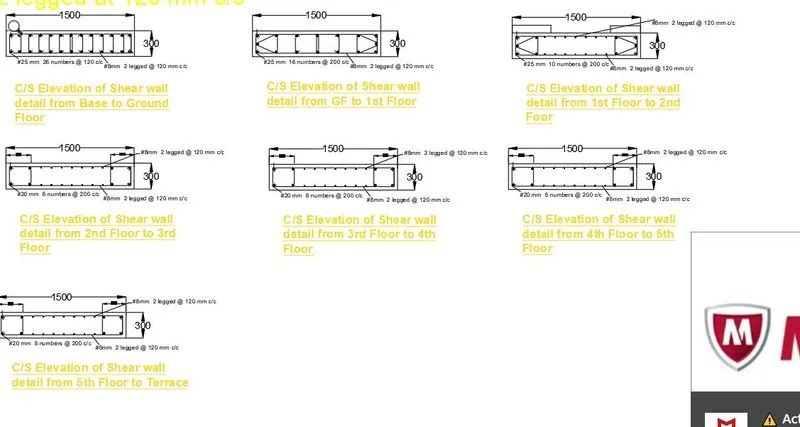
Elevation of Shear wall Detailing.