Analysis & Design of RCC shear walls in the model using ETABS
CHALLENGE - 9
ANSWERS
- AIM & INTRODUCTION:
- To Know the design of RC Shear wall using ETAB analysis.
- To know the basics of shear wall reinforcement details with respect to primary standards.
- To ensure the ductility reinforcement required as per IS 13920-2016 has been satisfied in reinforcement drawing.
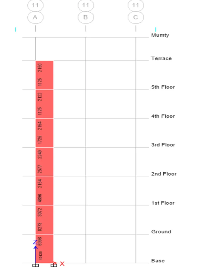
VERTICAL REINFORCEMENT OF SHEAR WALL AT GRID A-11 (mm2) FROM ETABS (300X1500)
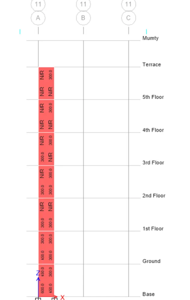
BOUNDARY ELEMENT WIDTH OF SHEAR WALL AT GRID 11-A (1000mm)
HORIZONTAL REINFORCEMENT OF SHEAR WALL AT GRID 11-A (mm2/mm)
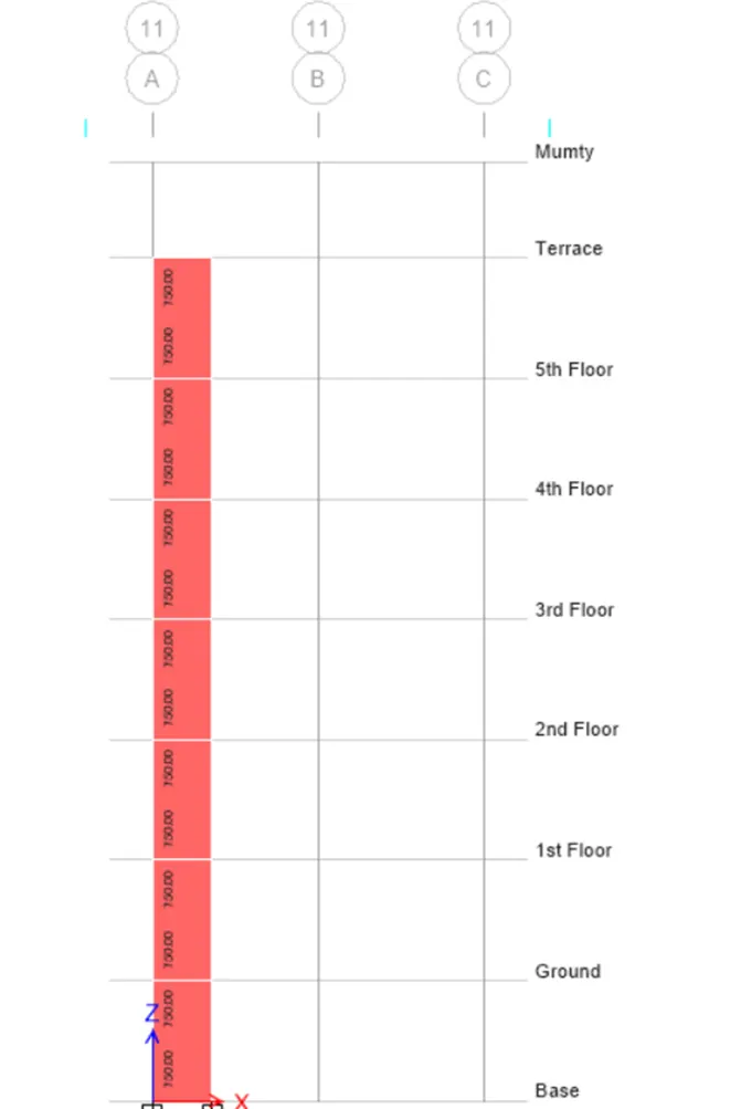
DETAILING GUIDANCE FOR SHEAR WALL :
Classification of shear wall as per IS 13920:2016:
As per clause 10.1.4


i.e 21000/1500 = 14 > 2
Hence Slender wall.
Minimum net vertical reinforcement as per IS: 13920:2016, Table 1. (iii)
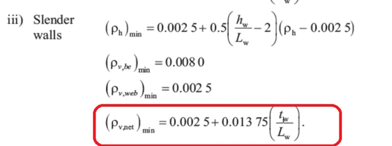
= 0.0025+0.01375 (300/1500)
= 0.00525 x(1500*300)
= 2363 mm2
Minimum vertical reinforcement with boundary element, Table 1. (iii)
= 0.008 x 600x300
= 1440 mm2 on left (600mm width boundary element )
= 1080 mm2 on right (450mm width boundary element )
DETAILING GUIDANCE FOR SHEAR WALL :
Minimum horizontal reinforcement of shear wall as per IS 13920:2016:
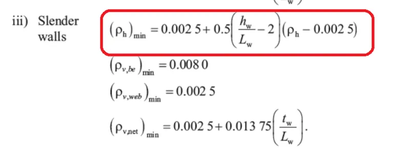
Ph = 750/(300x1000) = 0.0025
(Ph)min = 0.0025+0.5(21000/1500-2)x(0.0025-0.0025)
= 0.0025, Same as 750 mm 2
Maximum diameter of rebar for shear wall:
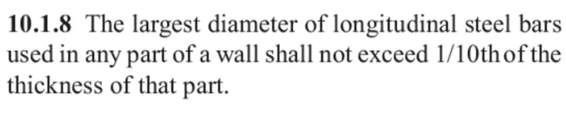
= 300/10
= 30 mm
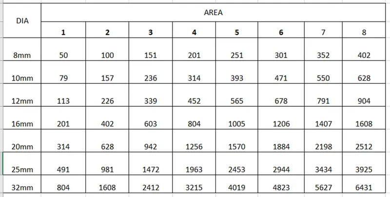
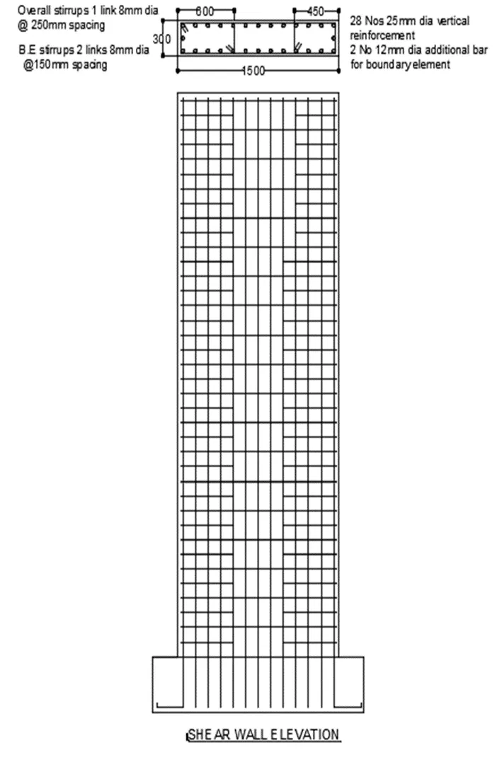
Adopt 25mm dia rebar in vertical reinforcement.
Detailing for confining reinforcement:
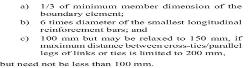
- 1/3 of 300 = 100mm
- 6 x 25 = 150mm
- 150mm
-
Maximum spacing of confining reinforcement in boundary element = 150mm
Confining reinforcement within boundary element as per IS 13920-2016.
= 0.05x150x1000x25/415
= 452 mm2
DETAILING OF SHEAR WALL AND BOUNDARY ELEMENT