Analysis & Design of RCC shear walls in the model using ETABS
DESIGN SHEELL WALL
elevation drawig of reinforcement
procedure:
- Extract values of longitudinal steel ratio, boundary element length and shear reinforcing ratio from the design results.
- Provide cross sectional steel arrangement of the shear wall from its base up to terrace, in compliance with provisions of IS 13920 – 2016.
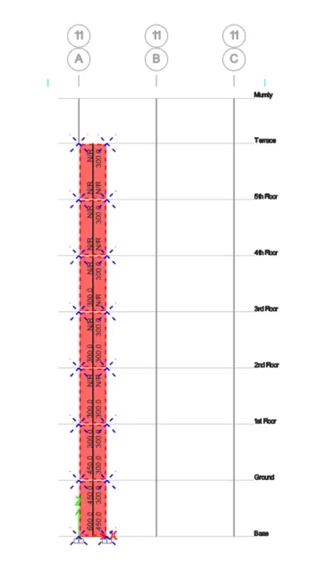
STORY DATA
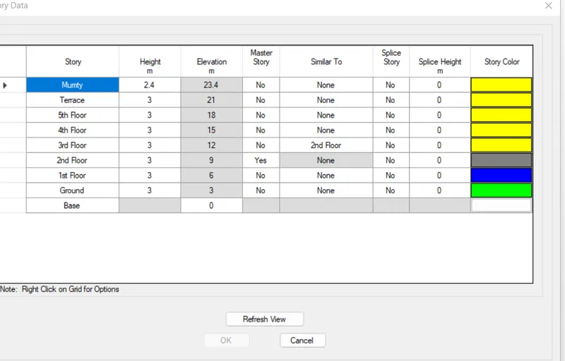
VERTICLE SHEAR WALL A11
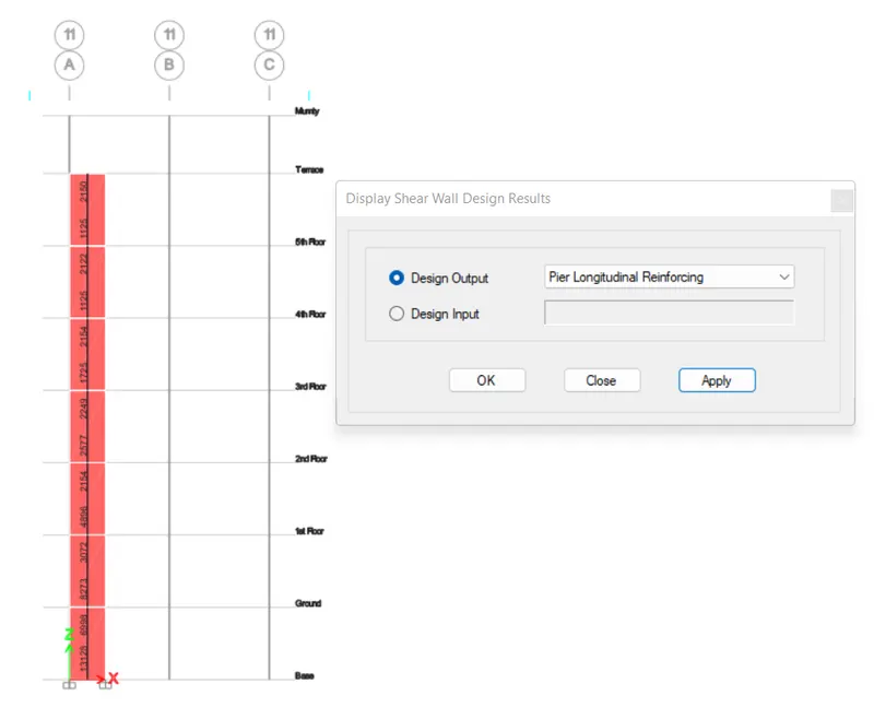
HORIZONTLE SHEAR WALL
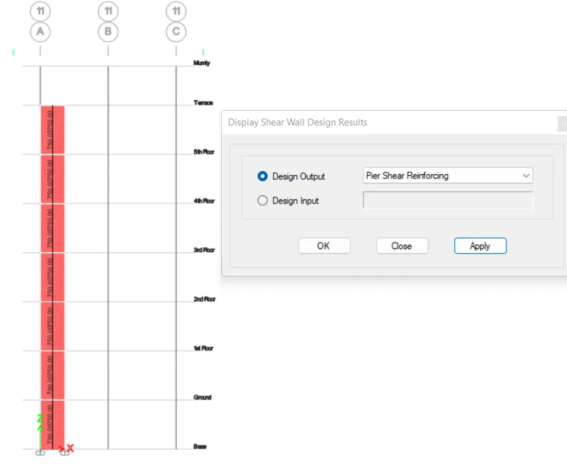
BOUDRY ZONE WIDTH
DETAILING GUIDLINES FOR SHEAR WALL
min reinforcement for shrinkAFE ANDtemp
ultimate limit state design rebar element} whichever is grater should be drawen in rc shear wall detailing
ductility rebar requirment
classification of shear wall as per IS-13920clause10.4 slender wall
hw/Lw=21000/1500=14>2
min net verticle reinforcement as per IS-13920-2016 table-1 -3 =2363mm2
0.0025+(300/1500)
min verticle reinforcement within boundry element table-1-3
1440mm2 on left (60mm width boudry element
1440mm2 on right (60mm width boudry element
MIn horizontle reinforceent in shear wall as IS 13920-2016 table 1-3
=750(300*100)=0.0025,hw=2100hw=2100Lw=1500
=0.0025+0.5(21/15-2)*0
=0.0025which is same as 750mm2
max dia of rebar for shear wall as per is =13920-2016 clause 10.1.8
commercial rebar dia 25mm shall be adopted
confining reinforcement spacing for boundry wall as per is -13920-2016 clause 10.4.4
- 1/3rd of min member dimention =300/3
- 6 times smallest main bar =6*25 =150mm
- 150mm permisible if verticle bars are spaced at max 200m
max spacing of confining reinforcement boundry element 150mm
confining reinforcement within boundry element as per is-13920 clause 10.4.4
resuly:
Ash=0.05Svhfck/fy
Sv =150mm
h=1000mm
Ash=452mm2
commercial rebar dia 25mm shall be adopted