Ahmed Body Challenge
AIM:-
- To simulate Ahmed's body in ansys fluent.
- To run the simulation for the velocity of 25 m/sec with the default air properties in fluent.
- To describe Ahmed's body and its importance.
- Explain the reason for the negative pressure in the wake region.
- Explain the significance of the point of separation.
- To create necessary plots for velocity, pressure and wake region.
- To perform grid dependence test and note the lift and drag coefficients.
SIMULATION AND EXPLANATION:-
GEOMETRY:-
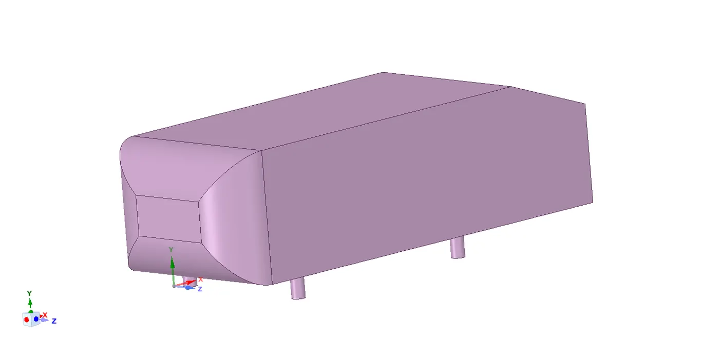
I have used the given geometry named Ahmed's body which is shown below.
Let's discuss the importance of ahmed's body.
- The Ahmed body is a generic car body (a simplified vehicle model). The airflow around the Ahmed body captures the essential flow features around an automobile and was first defined and characterized in the experimental work of Ahmed.
- Although it has a very simple shape, Ahmed body allows us to capture characteristic features that are relevant to bodies in the automobile industry.
- This model is also used to describe the turbulent flow field around a car-like geometry. Once the numerical model in validated, it is used to design new models of the car.
Above geometry dimensions are
Length:- 1.004m.
Height:- 0.288m
Width:- 0.389m
Cylinder pillars:- 0.05m
Slant angles:- 40 degrees
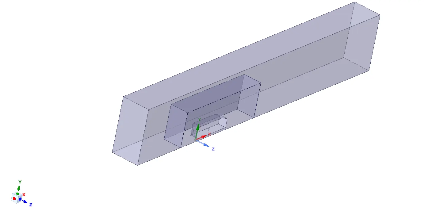
I have created two enclosures around the Ahmed body to capture the physics properly.
As the body is perfectly symmetry I am going to split the body into half using 'split body' command in the spaceclaim as shown in figure below.
MESHING:-
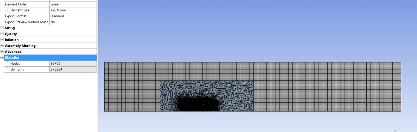
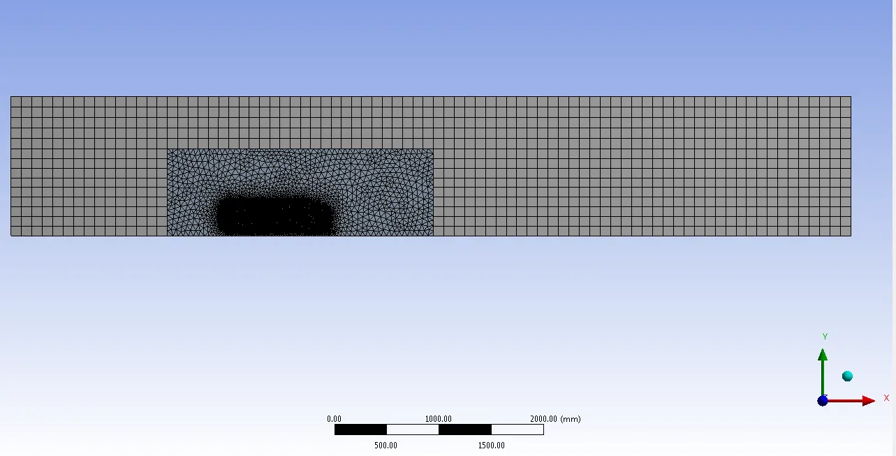
I am going to perform grid dependency test on this geometry so I have created three different caese, coarser to finer.
- The outer most enclosure have low number of cells.
- The enclosure around the Ahmed body (smaller) have a more number of cells
- The Ahmed body and the pillars are refined. I have also used inflation layers around the ahmed body.
- Named sections:- Inlet, Outlet, Car-ahmed body, Symmetry-upper face & side faces and Wall-bottom face(road)
CASE 1:-
No of elements:- 275254
No of nodes:- 86703
CASE 2:-
No of elements:- 307774
No of nodes:- 96269
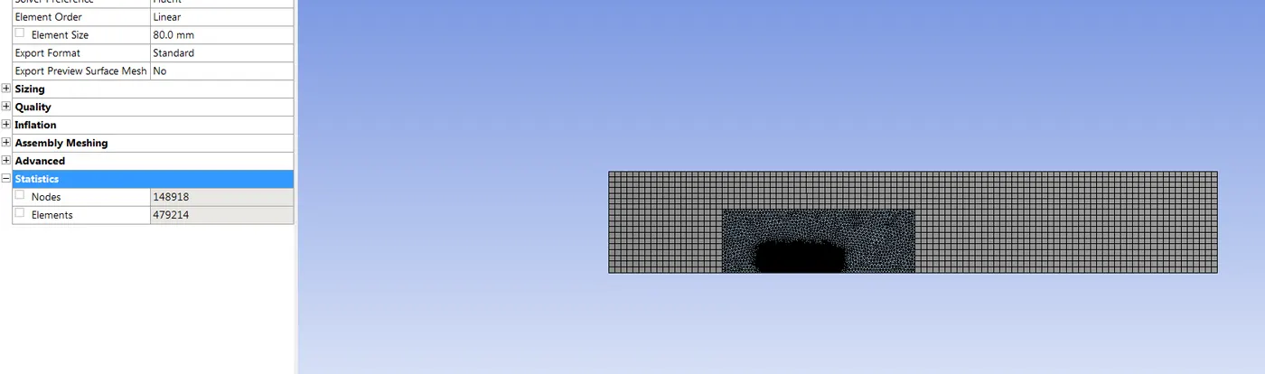
CASE 3:-
No of elements:- 479214
No of nodes:- 148918
CASE SETUP AND SIMULATION:-
Before setting up the case we have update the mesh, so that it gets updated in the fluent.
General setup:-
Solver type:- absolute velocity,Density based and Steady state.
Turbulent model used is K-epsilon model (energy turned on as temperature is effecteing here).
Hybrid initialization- 500 iterations.
Mayerial used is AIR.
Boundary conditions:-
Inlet velocity is 25m/s
Outlet pressure:- 1atm (0 guage pressure)
Wall with no slip condition.
Reference values are very important as we need lift and drag values here.
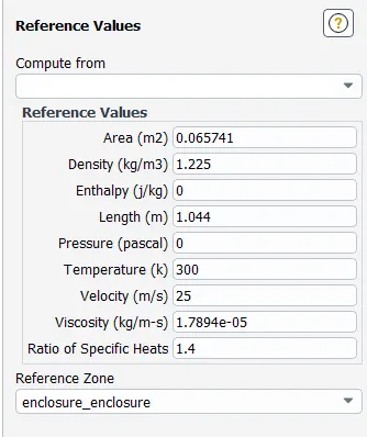
The area used here is preojected area which is calculate in the fluent itself.
Reports and contours:-
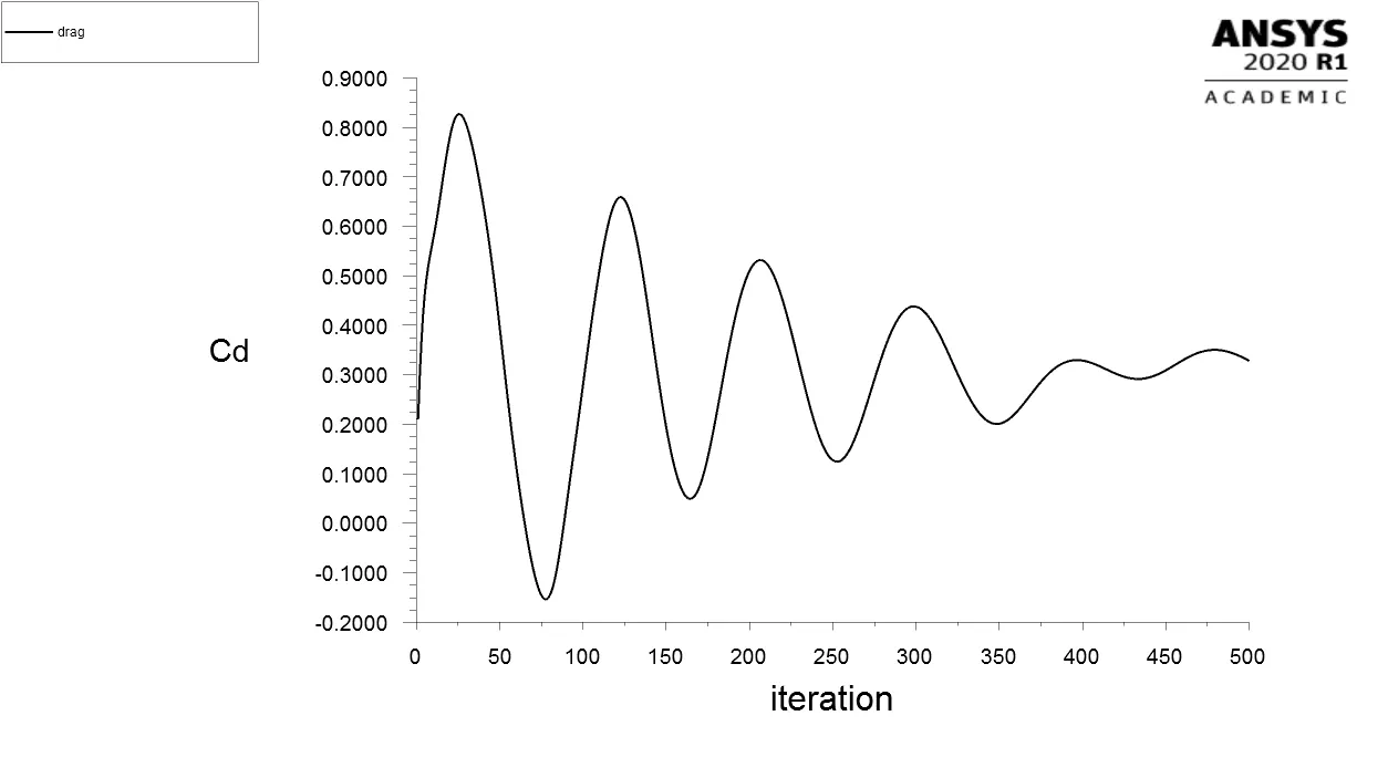
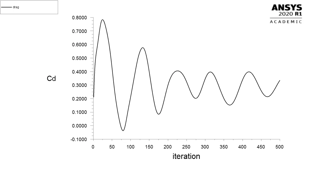
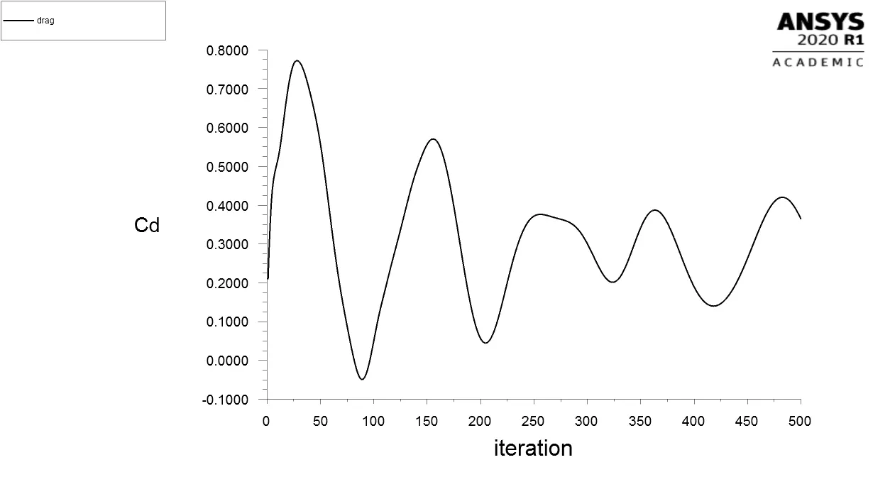
I have created the drag and lift reprots.
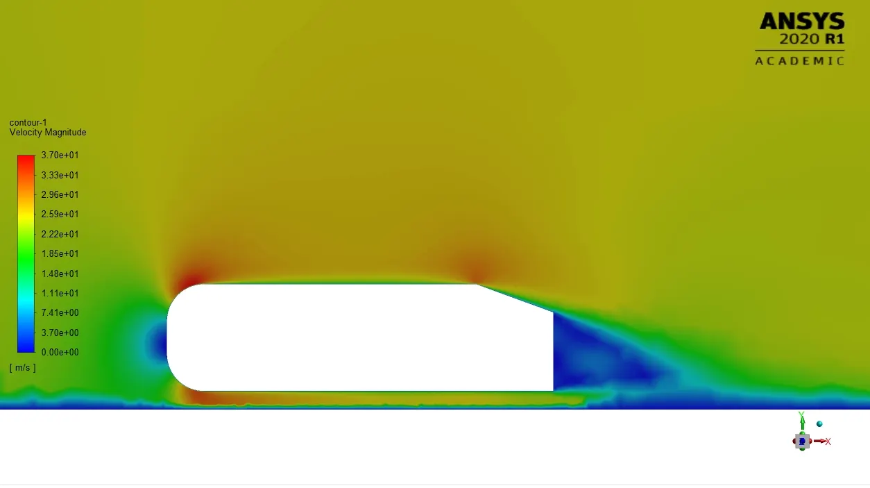
I have also created the velocity contour and animated it.
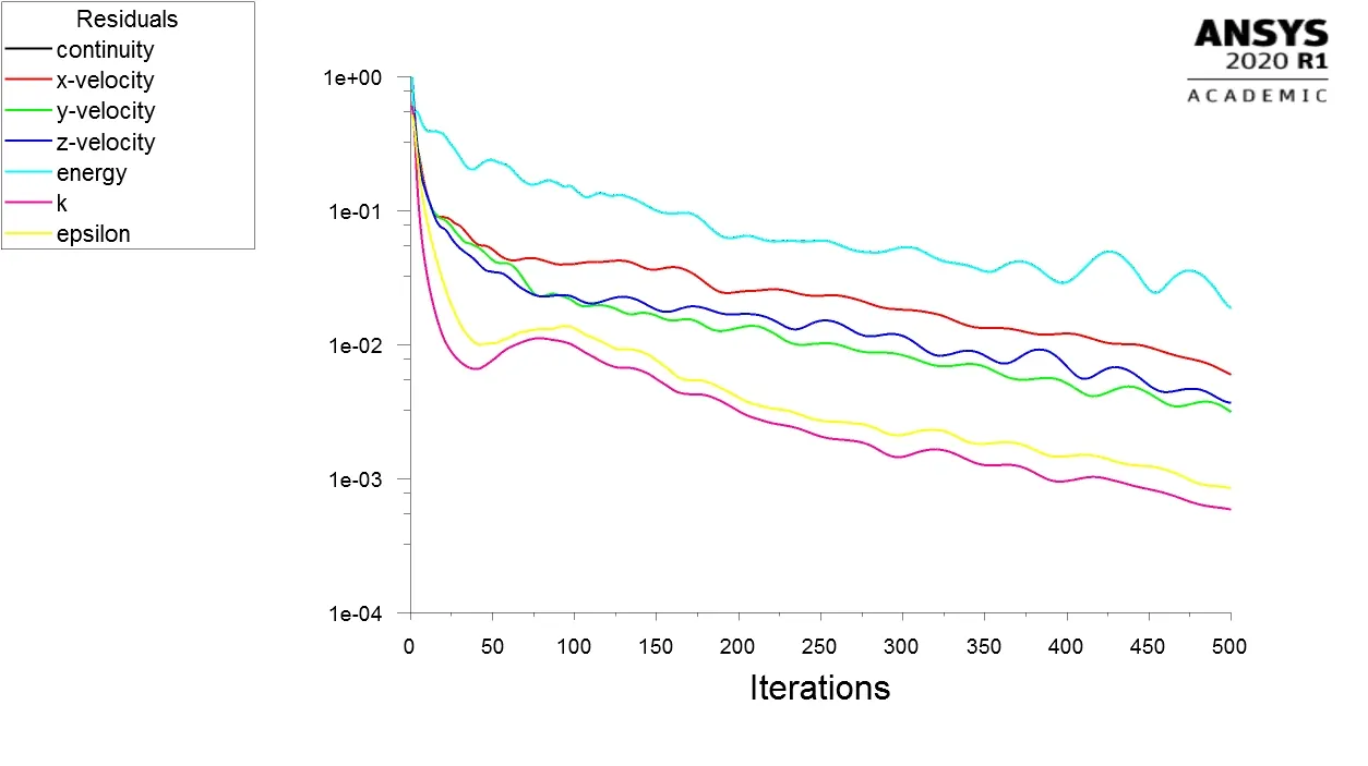
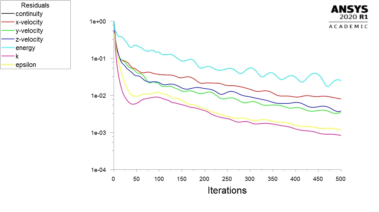
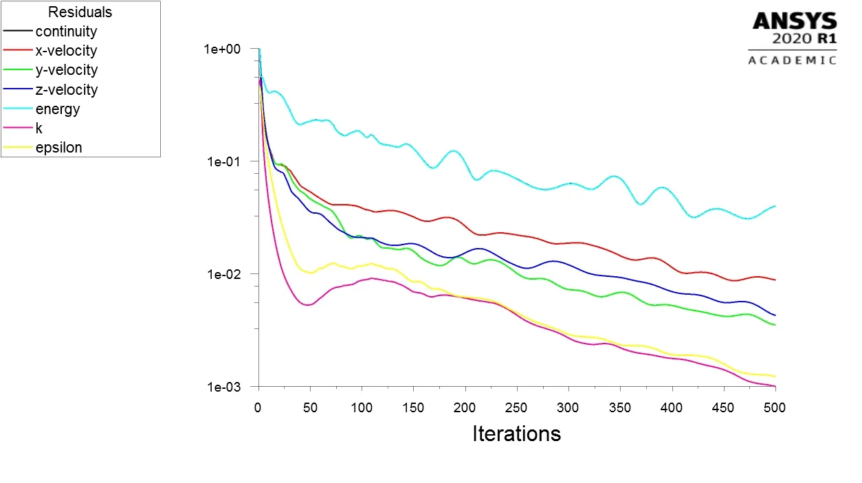
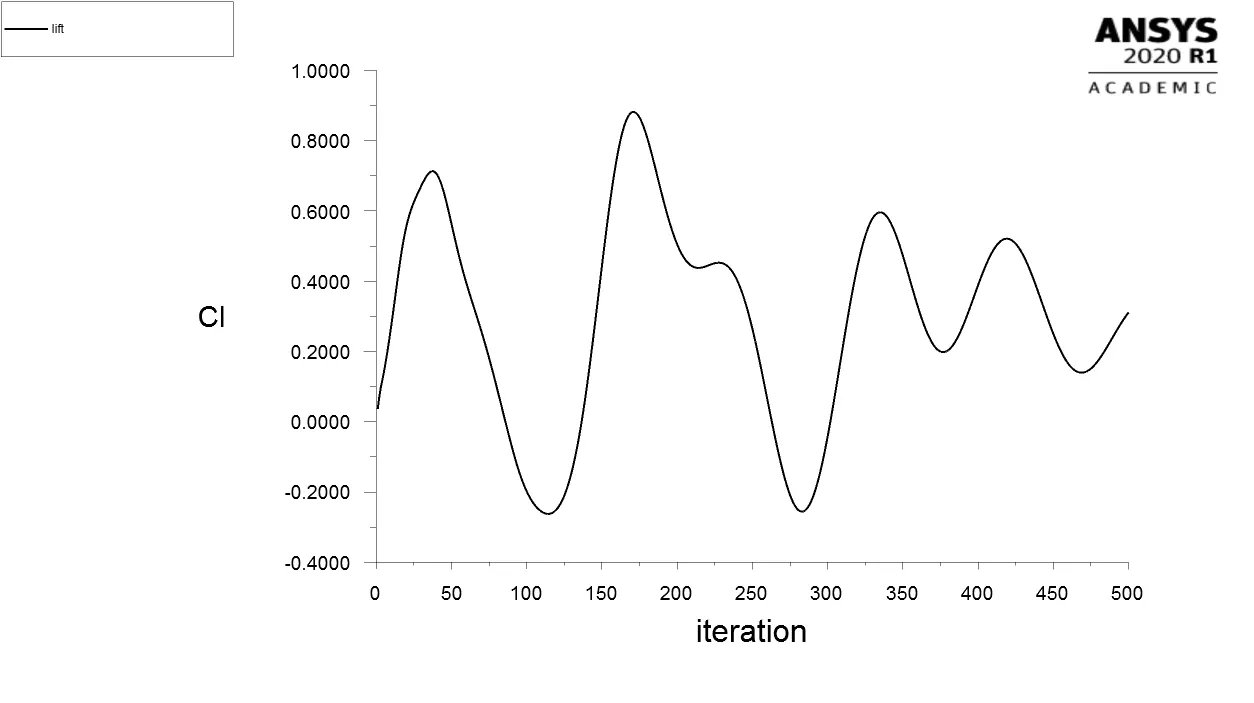
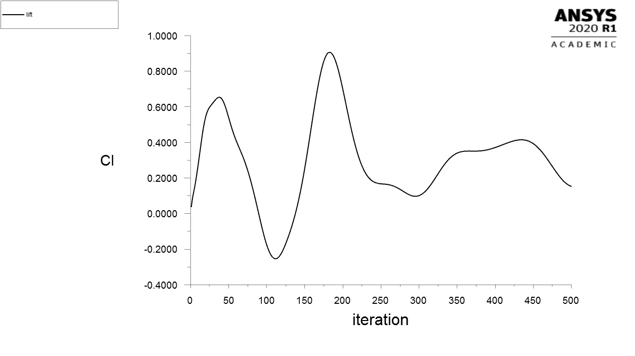
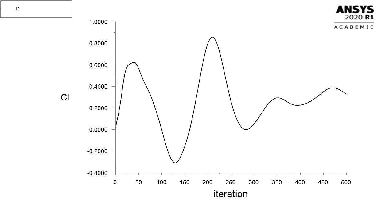
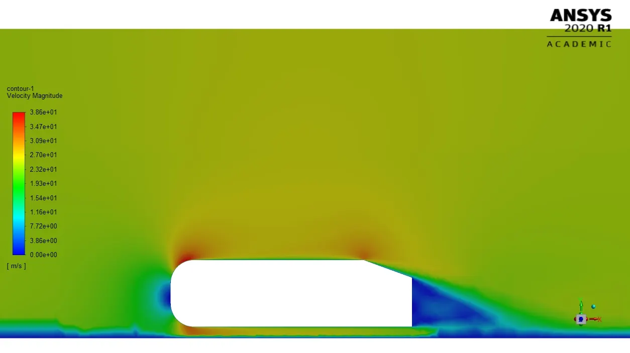
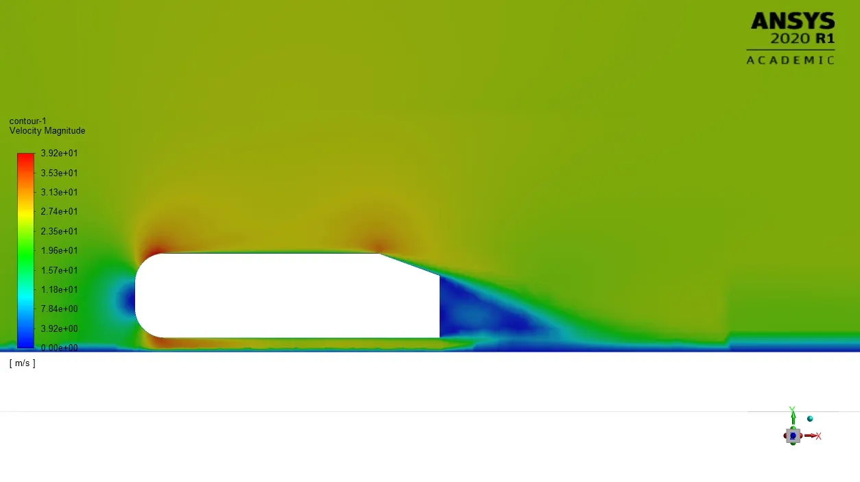
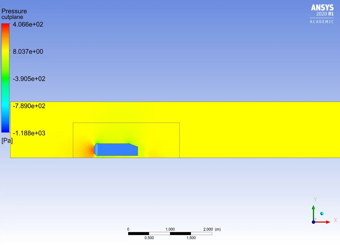
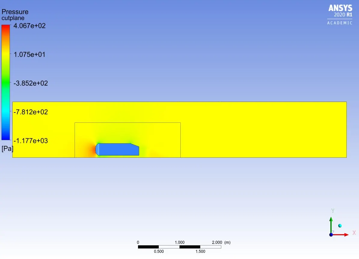
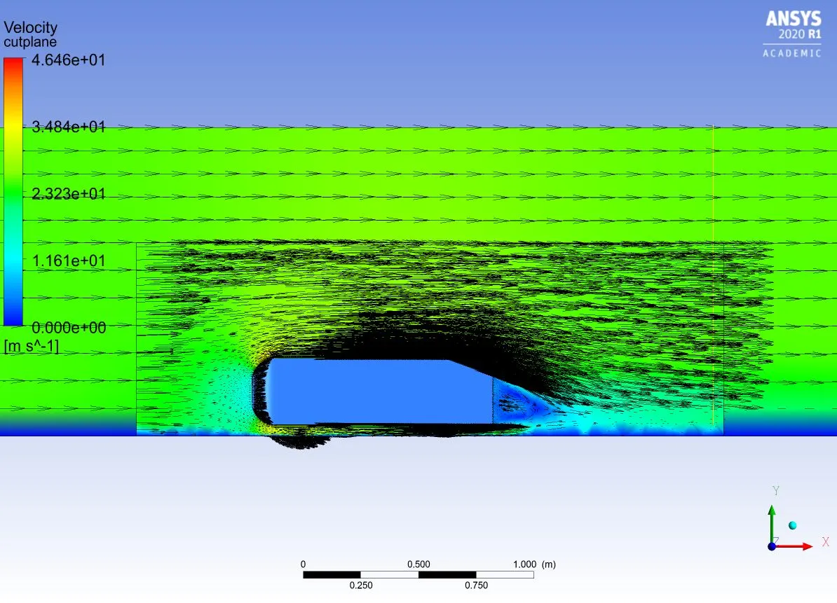
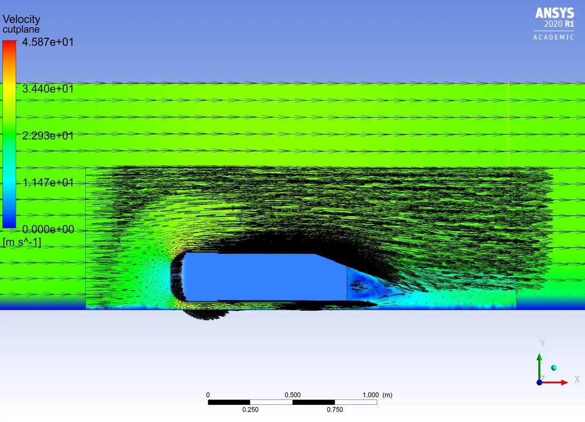
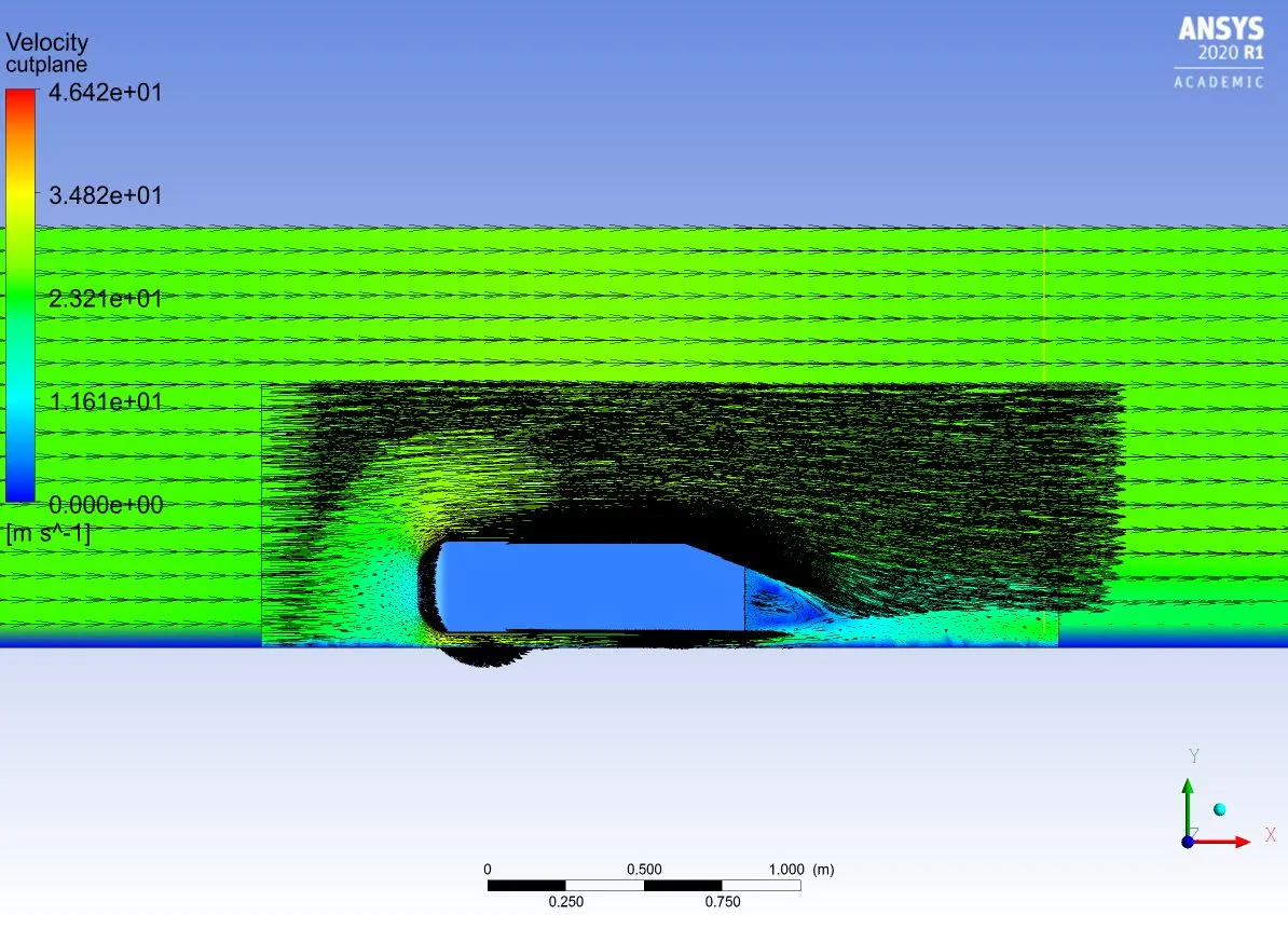
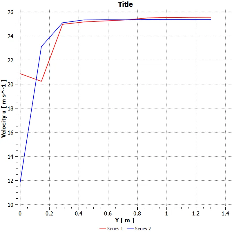
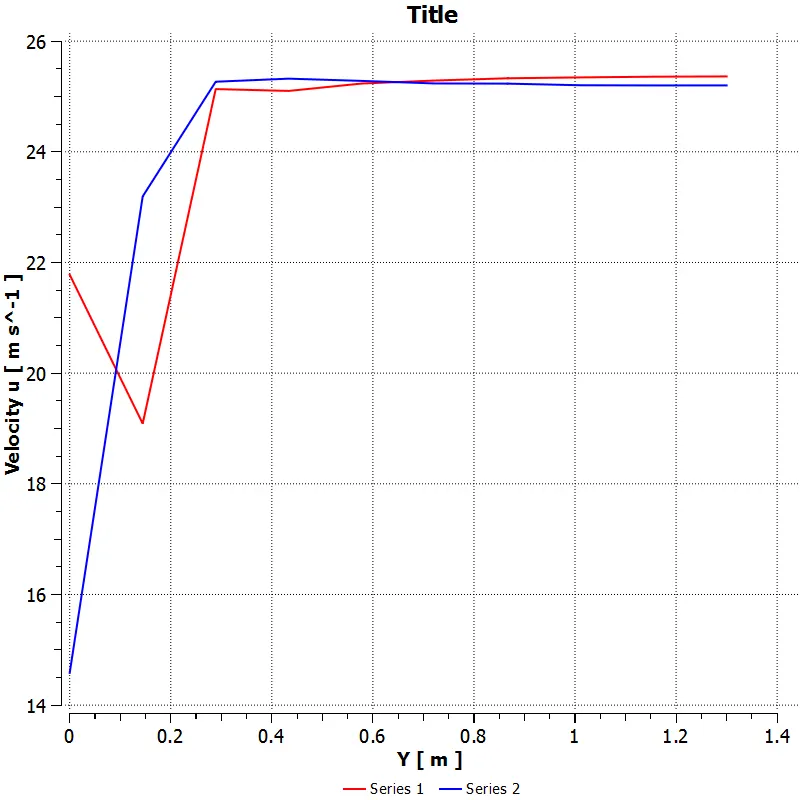
Note :- The plots below are in series for case 1 to case 3 respectively
RESULTS:-
Residuals:-
Drag:-
Lift:-
Velocity Contour:-
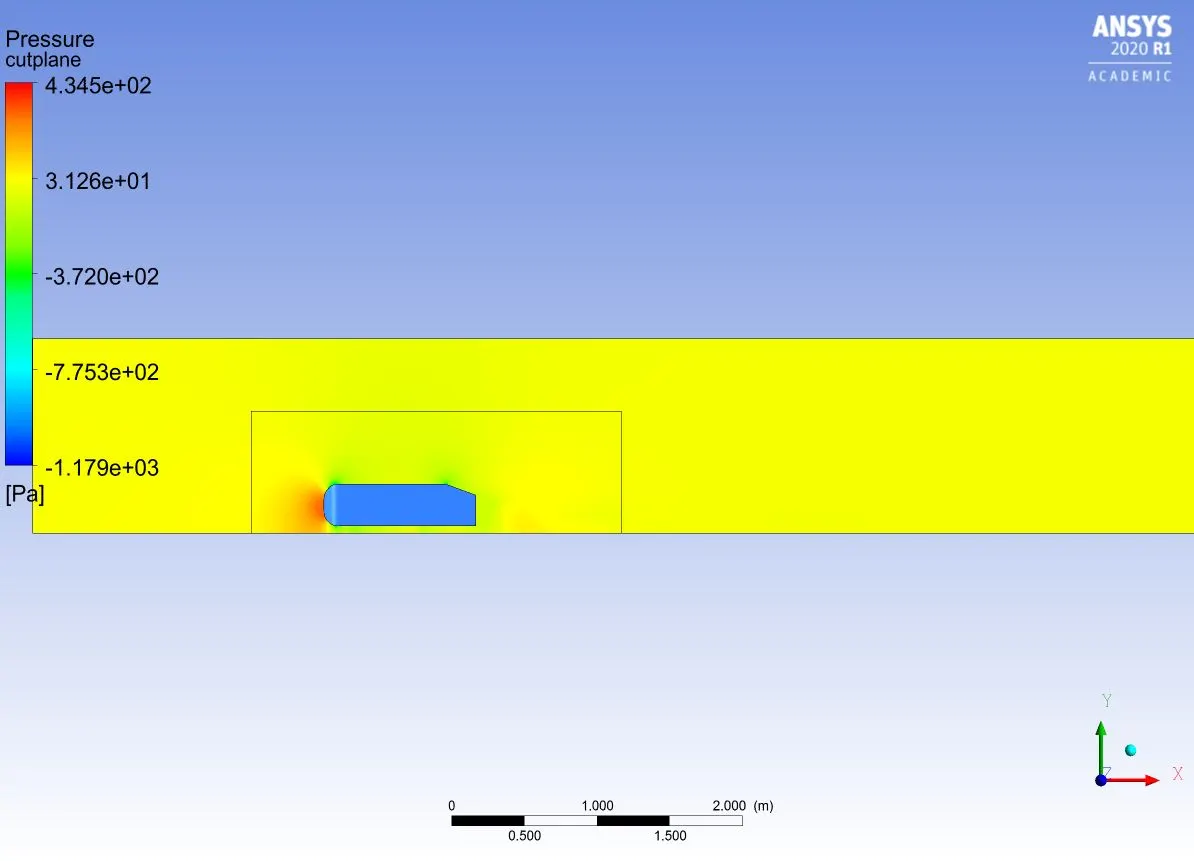
Pressure:-
Vector field:-
Wake region:-
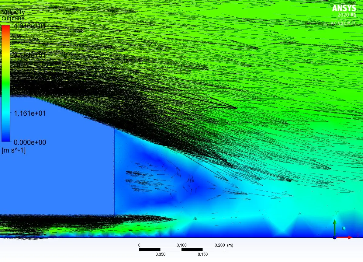
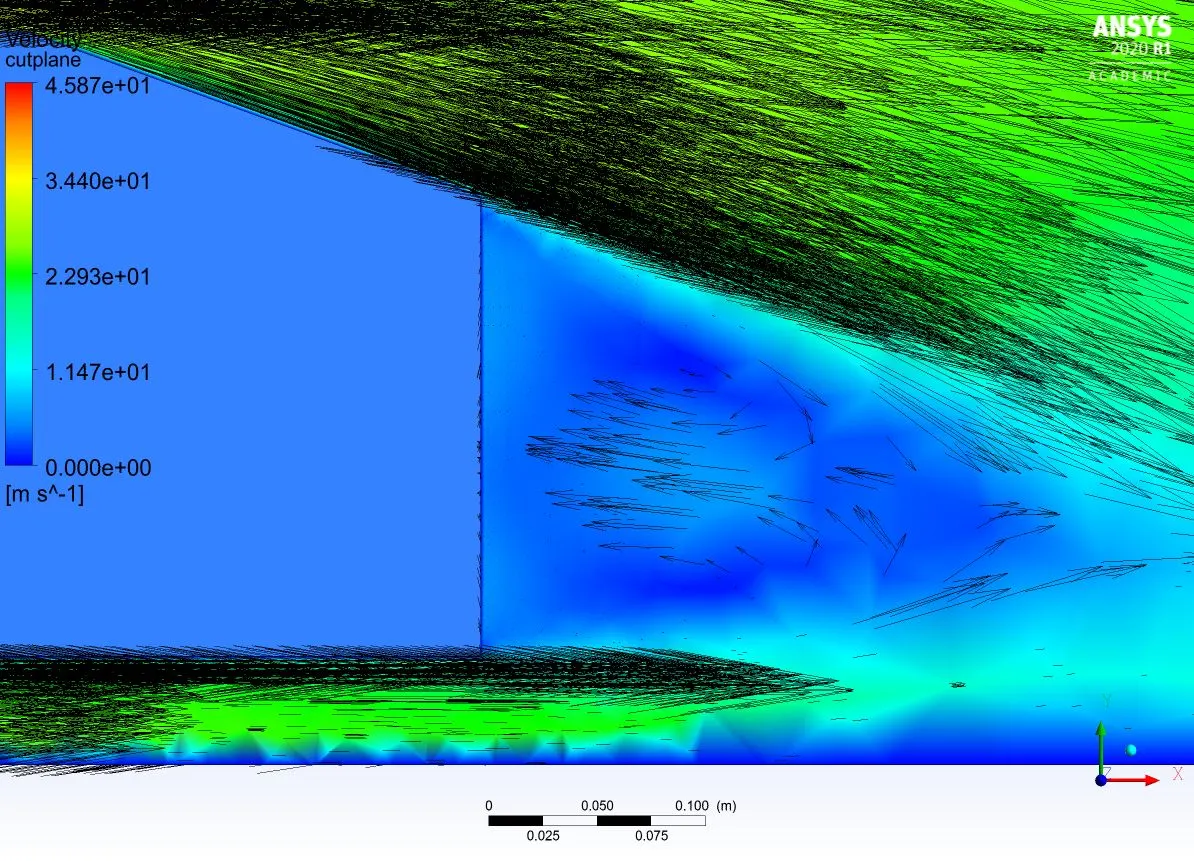
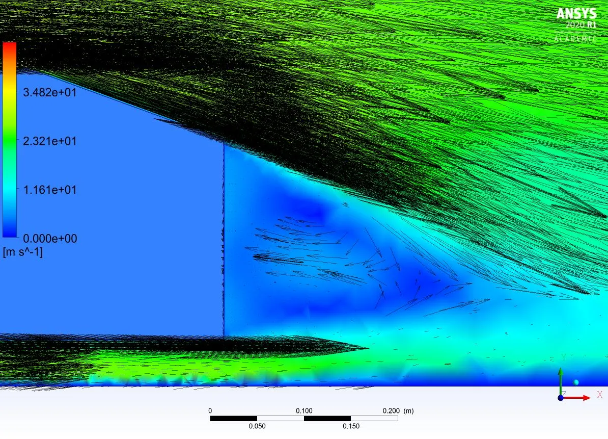
Chart:-
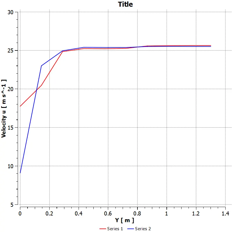
I have created two lines at a certain length so that we can capture the velocity change at the rear of the body.
CONCLUSION:-
I have performed grid dependency test and noticed few points which are mentioned below
- in the case 1 where the mesh is coarser. we cannot see the physics happening clearly compared to the other cases.
- In the case 2 where the mesh is fine enough, computational time and results were also handy.
- In the case 3 where the mesh is finer, we can see the physics clearly but the computational time was high.
| Grid Dependency | Cl | Cd | |
| CASE 1 | 0.31107974 | 0.32822545 | |
| CASE 2 | 0.15311341 | 0.33546295 | |
| CASE 3 | 0.32762699 | 0.36378558 | |
Why are getting negative pressure?
- The flow gets negative pressure where the velocity is high.
- Recirculation at the rear is also the reason to get negative pressure.
- The flow cannot turn backwardsat the rear end so it cretes a pressure gradient, it goes negative to contour balance the stress stress.
Significance of point of seperation:-
- Flow seperation is happening near the slant angle.
- As the slant angle increases the more pressure can be observed at the rear end.
- So if we can re-create the geometry to reduce this flow seperation, drag will be reduced and performance of the vehicle will be high.
- Fuel consumption can also be reduced if the body is streamlined.