Ahmed Body Challenge
Aim: To simulate flow across an Ahmed body in a virtual wind tunnel and obtain the coefficient of drag along with the velocity and pressure contours.
Description:
As the burning of fossil fuels becomes a more pressing issue, manufacturers are introducing more fuel-efficient cars to the market. One main contributor to fuel burn is the car’s aerodynamic drag. Complexly shaped, cars are very challenging to model and it’s difficult to quantify the aerodynamic drag computationally. The Ahmed body is a benchmark model widely used in the automotive industry for validating simulation tools. The Ahmed body shape is simple enough to model, while maintaining car-like geometry features. The Ahmed Body was first created by S.R. Ahmed in his research “Some Salient Features of the Time-Averaged Ground Vehicle Wake” in 1984. Since then, it has become a benchmark for aerodynamic simulation tools. The simple geometrical shape has a length of 1.044 meters, height of 0.288 meters, and a width of 0.389 meters. It also has 0.5-meter cylindrical legs attached to the bottom of the body and the rear surface has a slant that falls off at 40 degrees.
Geometry:
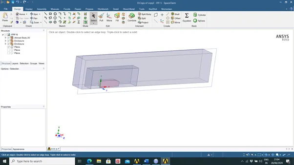
The geometry was created using SpaceClaim and due to the symmetric nature of both the flow and the Ahmed body itself the geometry was cut into two halves and only one half was simulated. This reduces the computational load placed on the computer and allows for more accurate results to be obtained.
Mesh :
The appropriate mesh was chosen after a series of experimental meshing condiditons to demonstrate that the results were not largely dependent on the mesh.
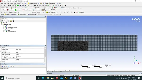
An external cuboidal box was created for simulating the external flow and the ahmed body was imported into it . An exclosure was created inside , enclosing the ahmed body , this volume was given a finer mesh in order to obtain accurate results.
Mesh Dependence Test-
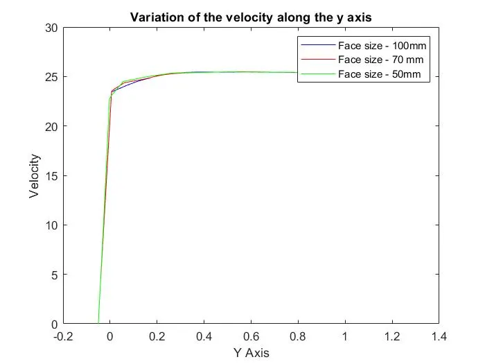
Three meshes were used and in those the face size of the mesh elements on the outer body was reduced from 100 to 50 and the value of the velocity along a line , 2m from the intake and perpendicular to the x-z plane was used to compare the mesh results . The plot attached here shows that the variation in velocity magnitude was negligable and further refinement was not required.
Mesh:1 Face size - 100m and 87417 elements
Mesh:2 Face size - 70mm and 100798 elements
Mesh:3 Face size - 50mm and 130533 elements
Case I : 0.3361
Case II :0.366
Case III: 0.363
The difference in the values of Cd inthe case 2 and 3 are small indicating that the value has converged .
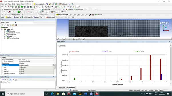
Final Mesh:
Solution and post-processing
The k-omega SST model was used. This was because to determine coefficient of drag an accurate result was needed near the ahmed body’s walls. The case was run in a steady state solver with inlet velocity of 25m/s for 200 iterations the results in form of velocity and pressure contours along with a vector plot.
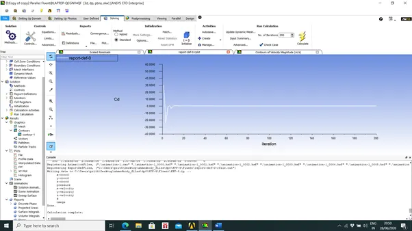
The value of coefficient of drag – 0.363
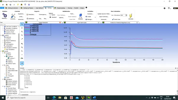
Residual plot
Convergent plot of Cd
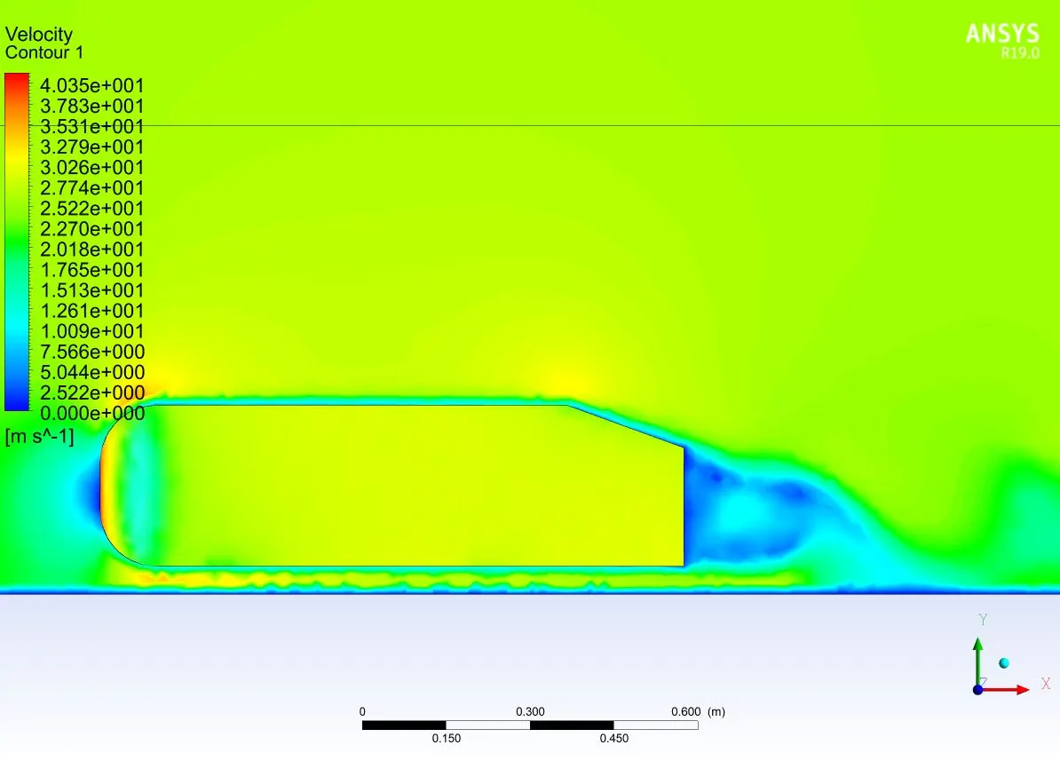
Velocity contour illustrating the formation of wake region behind the Ahmed Body.
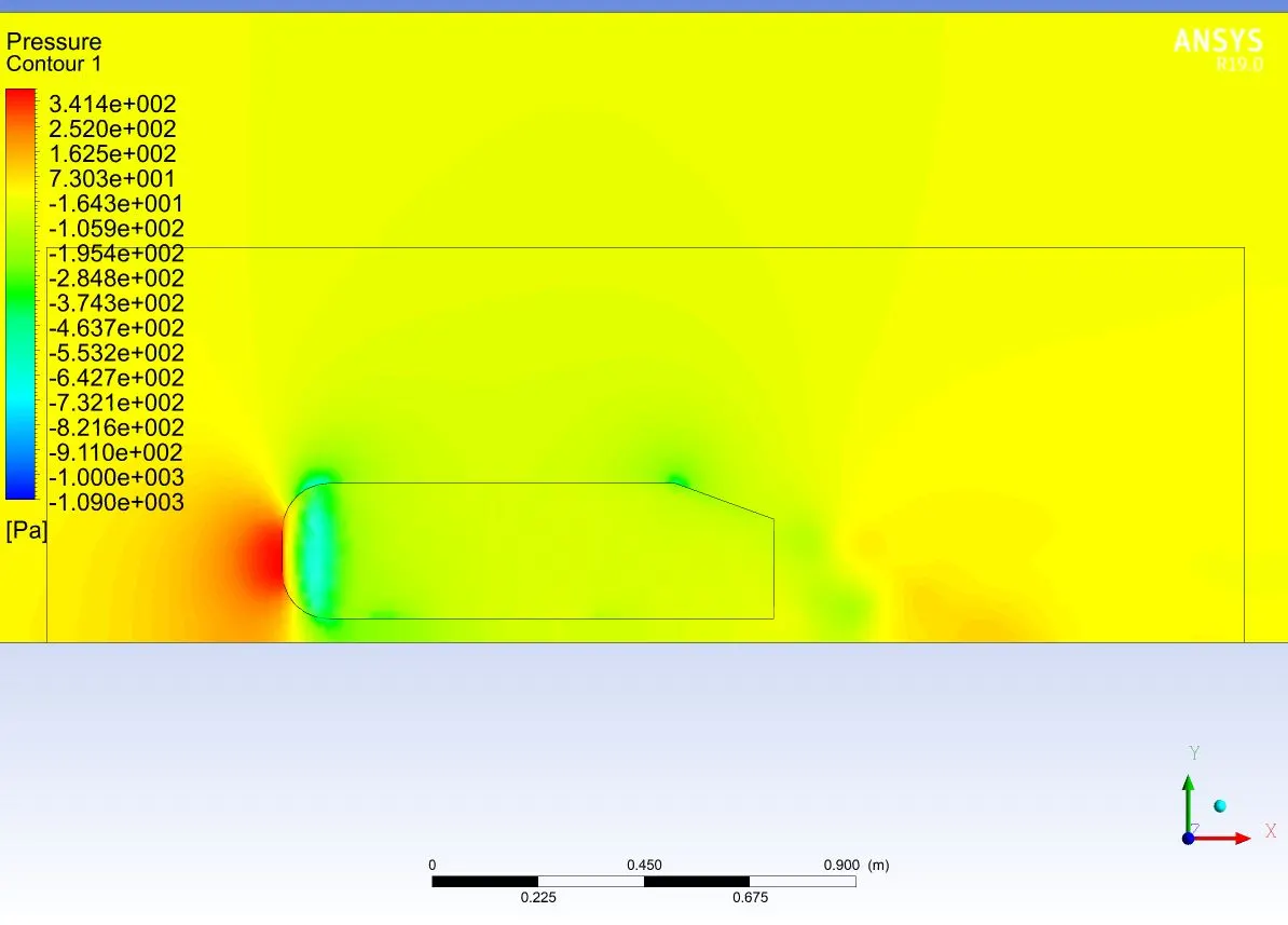
Pressure contour
Vector plot of velocity
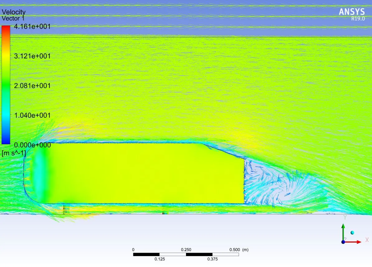
There are regions in the Ahmed body where the pressure is below zero – or below atmospheric pressure. This is due to the velocity increasing in magnitude as the air flows over the Ahmed body. Also, behind the Ahmed body there is wake formation (flow recirculation) that results in pressure reducing below zero. The blunt shape of the top of the Ahmed body results in flow separation and consequently the pressure reducing below zero.