Ahmed Body Challenge
Aim :- Numerical simulations on the aerodynamics of the Ahmed body.
Abstract :-
The aerodynamic behaviour of the Ahmed body is investigated experimentally and numerically. The experiment cover the slant angles of `20^o` for ahmed body. The commercial CFD tool `Fluent^(TM)`v6.3.26 is tested for its ability to reproduce the aerodynamic force coefficients of the body. The simulations are validated with the present experiments and experiments from literature(research paper). Fair agreement with data from literature is found for velocity profiles along the slant and in the wake of the body.
Introduction :-
Ahmed body :-
Ahmed body is 3D representation of aerodynamic vechicle prototype which has same shape as that of real vehicle. The purpose of Ahmed body is that it helps in providing us needful data like drag coefficient,lift coefficient and pressure at the surface of body with the help of which we redesign and develop the prototype for real vehicle without wasting useful time and money.
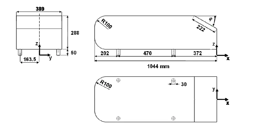
The Ahmed Body was first created by S.R. Ahmed in his research “Some Salient Features of the Time-Averaged Ground Vehicle Wake” in 1984. Since then, it has become a benchmark for aerodynamic simulation tools. The simple geometrical shape has a length of 1.044 meters, height of 0.288 meters, and a width of 0.389 meters. It also has 0.5-meter cylindrical legs attached to the bottom of the body and the rear surface has a slant that falls off at 40 degrees.
Optimized external car aerodynamics is necessary to achieve efficient vehicles with minimized fuel consumption, `CO_2` emissions, and noise, while keeping a good driving stability. Steadily increasing computer power has been raising the importance of simulating the external aerodynamics of vehicles and computing the corresponding aerodynamic characteristic numbers. At present, an efficient resource management gains increased importance everywhere. A substantial part of the development time of cars is therefore invested in optimization. This is possible only and particularly by virtual development. In order to establish such development processes in the car industry, reliable simulation models validated by experiments are needed.
Model experiments suitable for providing validation data make use of model bodies with geometries characterized by variable parameters, such as the slant angle at the back. One such body is the Ahmed body, a bluff model body of simple shape with basic aerodynamic properties of a vehicle, which has been used for many reference investigations. The first measurements on the influence of the slant angle of `20^o` at a flow velocity of 25 m/sec were carried out using a slightly different geometry, the so-called Morel body.
Ahmed body geometry with dimensions :-
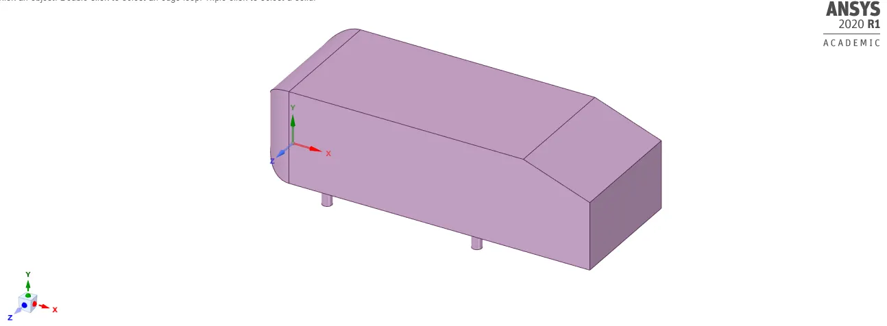
Dimensions of Ahmed body
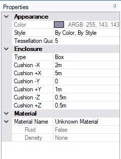
Ahmed body with enclosure
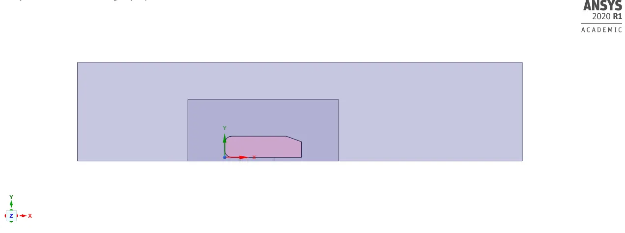
Details of enclosure of Ahmed body
1. Dimensions of inner enclosure 2. Dimensions of outer enclosure
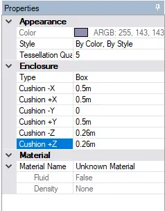
Preprocessing and solver setting :-
1. Mesh generation in Design-modeler
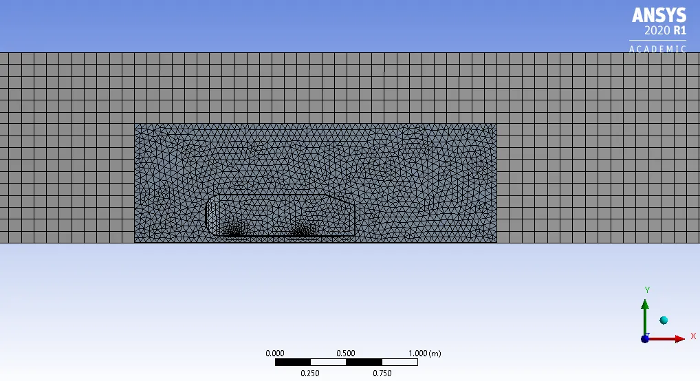
Table for different mesh size used for Ahmed-body :-
| Elements | Nodes | |
|
Case 1: Grid size of 100 mm for outer enclosure with Grid size of 50 mm for outer enclosure |
35789 | 107729 |
|
Case 2: Grid size of 90 mm for outer enclosure with Grid size of 40 mm for outer enclosure |
50928 | 171365 |
|
Case 3: Grid size of 80 mm for outer enclosure with Grid size of 30 mm for outer enclosure |
87840 | 344117 |
First layer thickness for inflation layer was calculated in this way :-
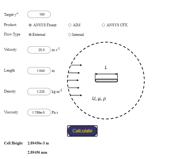
Hence, Total thickness for inflation layer was:- (2.9)*1.2^(4)=6.02mm.
2. Boundary conditions with modelling approach :-
Initial condition :-
Pressure:- 101325 Pa
Solver setup :-
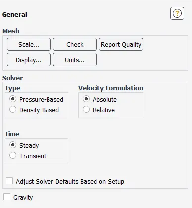
Here, We assumed steady state simulation with pressure based solver.
Boundary condition:-
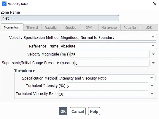
A. Inlet :-
B. Ahmed body :-
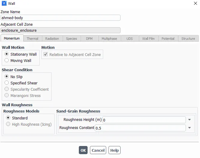
Here We assumed no slip condition at the walls.
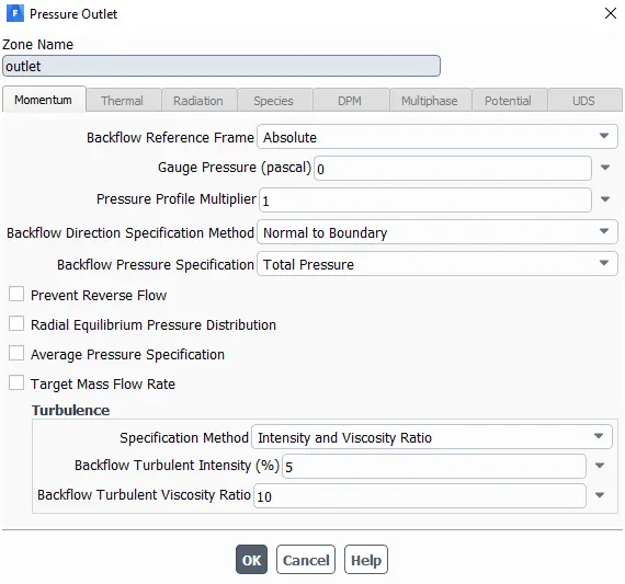
C. Outlet :-
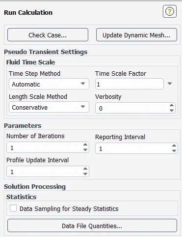
3. Run-time parameters :-
Post-processed results :-
For mesh size of 100 and 50mm for outer and inner enclosure respectively.
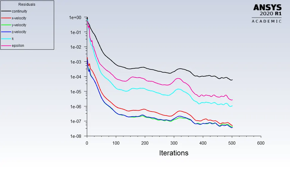
Residual plot
Velocity Contour
Pressure Contour
For mesh size of 90 and 40mm for outer and inner enclosure respectively.
Velocity Contour
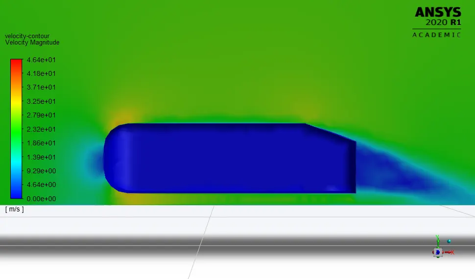
Pressure Contour
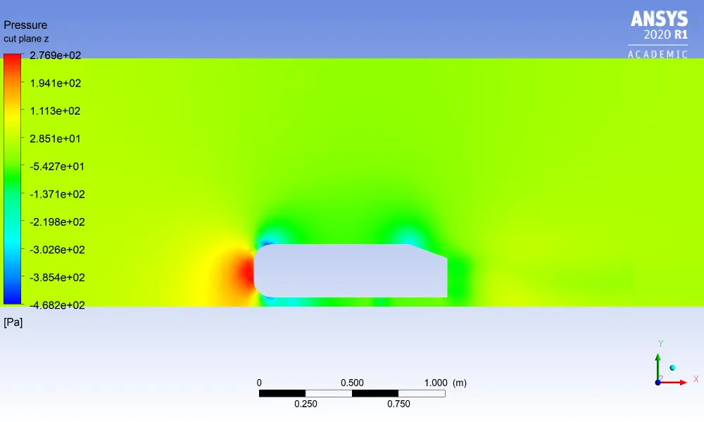
For mesh size of 80 and 30mm for outer and inner enclosure respectively.
Velocity Contour
Pressure Contour
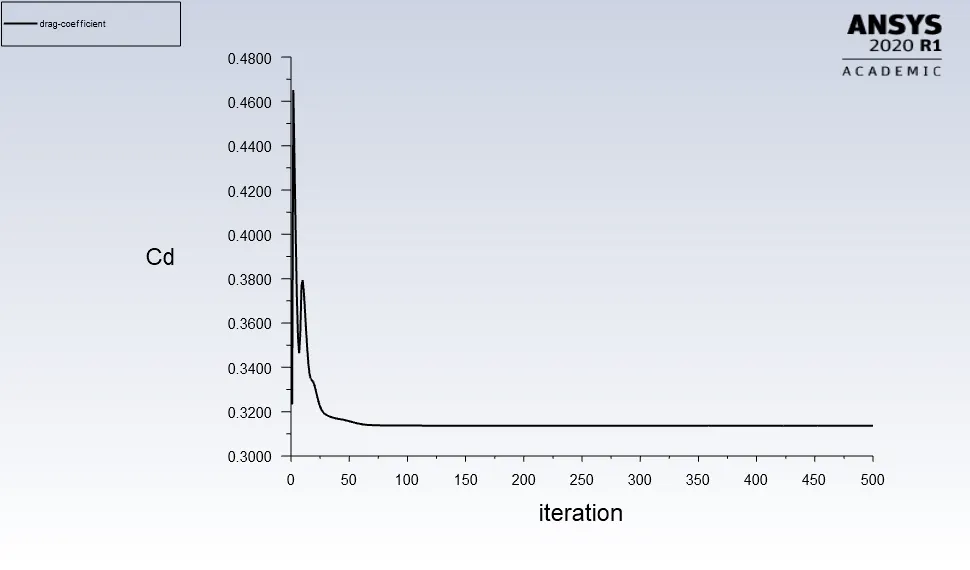
Drag coefficient for a refined case:-
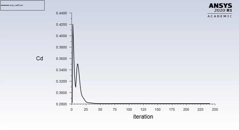
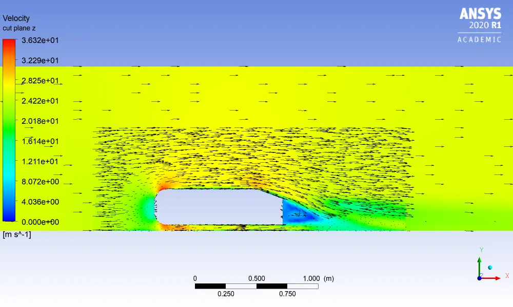
Velocity contour with vector plot showing wake region :-
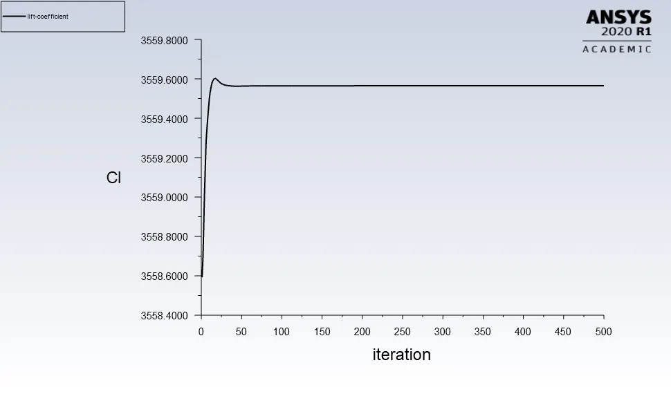
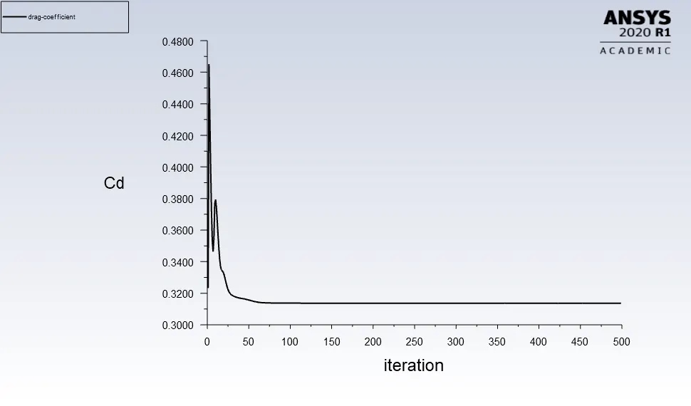
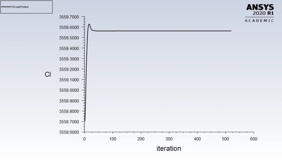
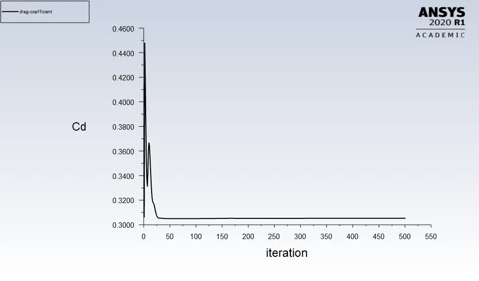
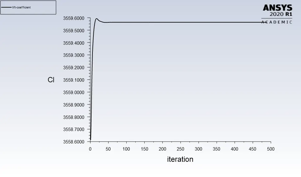
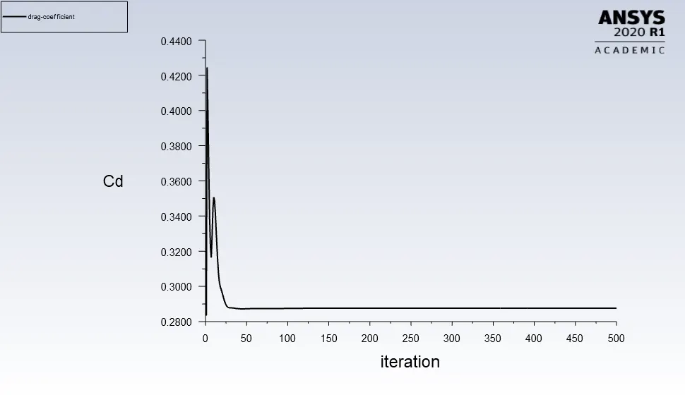
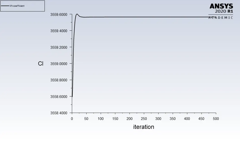
Lift and drag coefficient for each case of mesh size for Ahmed body :-
Case 1 :-
Case 2 :-
Case 3 :
Observation and explaination :-
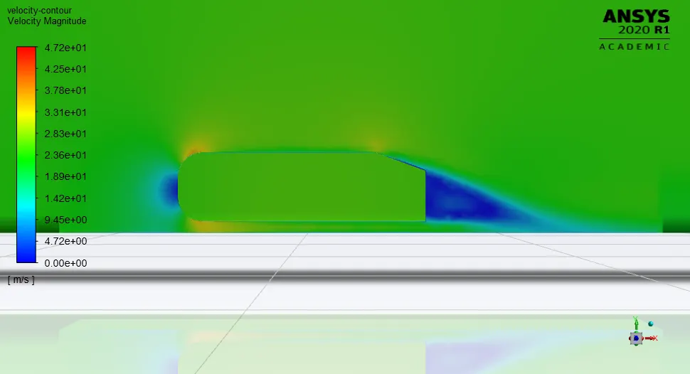
Here We observed that a wake region(a large recirculation region) have established at the rear side of Ahmed body in velocity flow Which have created a vortex flow at rear side. The reason behind the creation of such wake region is turbulence which has peak value of turbulent kinetic energy at the centroid of the vortex.
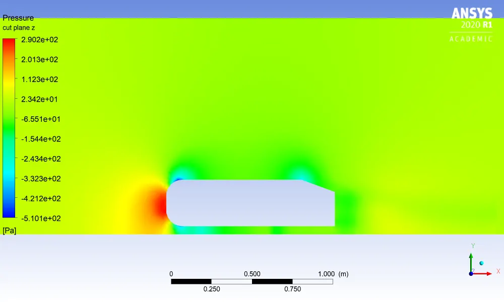
Here We observed that in the wake region, a negative pressure have been orginated. This is because of recirculation region that have been developed at the rear side of the Ahmed body. Now, the fluid particles in this wake region have turbulent kinetic energy which causes a force on certain area of Ahmed body at the rear side. Since force is acting on some portion of area of Ahmed body, We see a negative pressure in this region.
Now, Apart from this wake region, We see other two small recirculation zones at curve edge of front side and the slant edge of the Ahmed body in pressure profile Known as point of separation. The point of separation is again due to the turbulence in the region. The significance for this point of separation is that it leads to deattachment of flow in the fluid which causes a sudden dropwise in stream velocity and even becomes zero at the centre of vortex in wake region. The impact of this point of separation is that it has affected flow upto 200mm of distance from rear side of body.