AHMED BODY CHALLENGE
AIM:
To perform a Ahmed body simulation for the corresponding symmetry boundary condition in fluent.
INTRODUCTION:
Ahmed body is the simple bluff type body used for flow analysis.
A 3D model that represents standard passenger car.Here flow to be simulated outside the Ahmed body and the body is perfectly symmetric, so we run the simulation by considering the only half body. It results to save on the number of cells and get the results faster as well.
THEORY:
AHMED BODY:
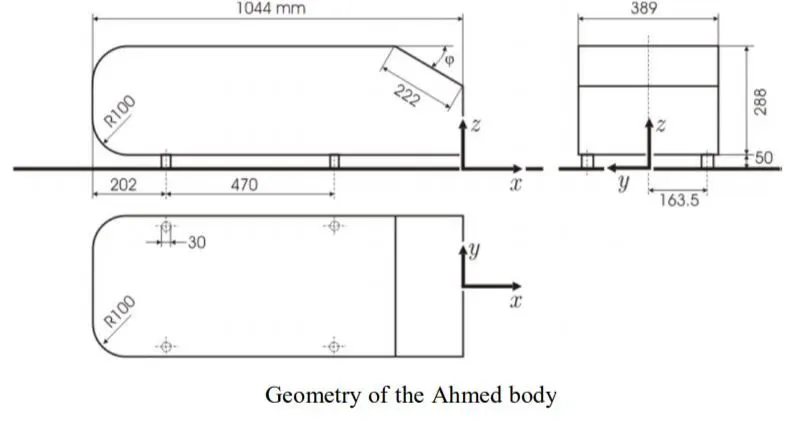
Ahmed body is simplifier car body,a ground vehicle is considered in which is used as test vehicle in industry.
Ahmed body is made up of round front part,a moveable slant plane placed in rear of body in a enclosure.
Air is used as working fluid,inlet velocity is `25m/sec,k-omega SST`model is used.
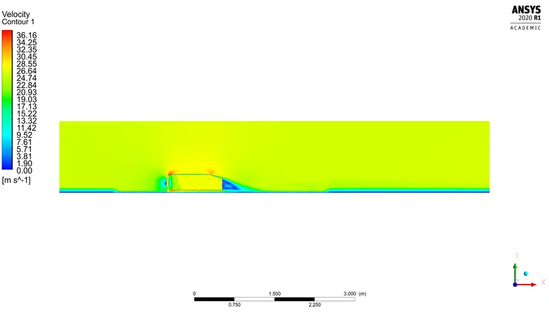
Results are present in form of drag coefficient value and flow field which includes velocity contour.
Actually in developing new road vehicle,its essential for designer to understand thoroughly structure of flow around the vehicle.
CFD suficiently enables to calculate quantities such as drag and lift for a road vehicle.
As wake seperation flow behind the ahmed body is the main contributor to the drag force,accurate precision of seperation process and wake flow are the key to successful modelling of this case.
Drag is important to be reduced in order to improve fuel efficiency and reduce the weight of vehicle.On the other hand,lift is critical at high speeds.Hence these two parameters are need to be carefully balanced.
Instead of meshing complete domain,meshing is done on the 2nd enclosure.i.e., around the ahmed body.
Set of cells that actually follows the shape of surface quiet closely are called as inflation layer.
Base lines mesh are done as its not accurate and case runs quickly to check setup.
Run the simulation for the velocity of 25 m/sec with the default air properties in fluent.
GEOMETRY SPACECLAIM:
AFTER USING SPLITBODY COMMAND:
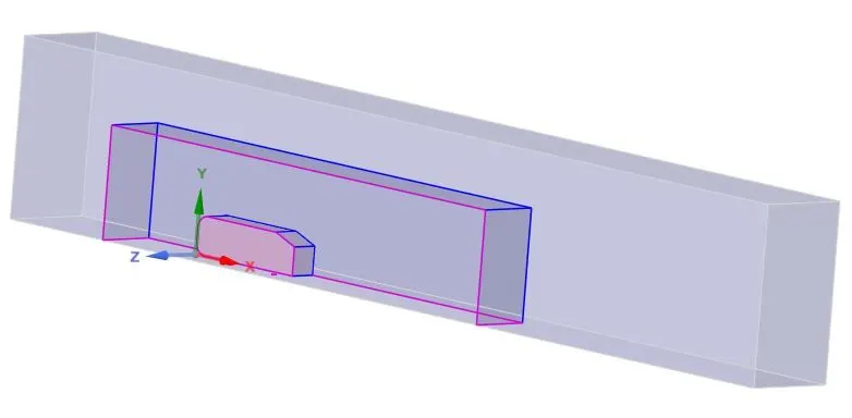
Split body command is used to reduce the cell count.
Spaceclaim creates d asingle voulme automatically by taking a alarger volume and subtracting volume of ahmed body.
Then add region of refinement,infront of ahmed body.So enclosure is created.
Enclosure is a tool used to enclose the bodies of a model so that the material enclosing the bodies can be assigned to something such as a gas or fluid.
There may be overlapping region. To avoid,Interference is created. Thus it made a perfect structure of straight lines to share information.
MESH:
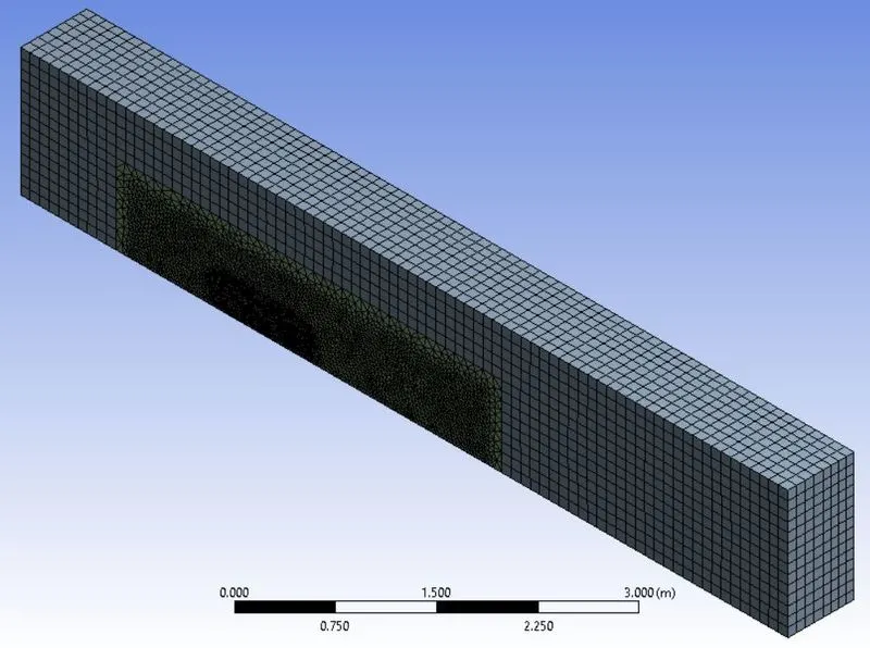
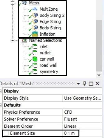
Mesh is generated with an element size of 0.1m.
Multizone is created to automatically generates a pure hexahedral mesh where possible and then fills the more difficult to capture regions with unstructured mesh.
Body sizing has been made for two bodies with an element size of 0.035m and 0.02. i.e., ahmed body and near enclosure.
Edge sizing has been created on ahmed body of four edges with 25 number of divisions.
Inflation layer is created i.e., creating set of cells that follows the shape quiet closely
Named selection are inlet,outlet, car wall, road wall, symmetry.
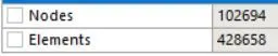
CELL COUNT - 428658
SETUP:
Pressure based solver. i.e., mach number = inlet flow velocity/sound of speed velocity.
m = (25/300) m/s = 0.08m/s
If mach number is less than 0.3, prsseure based solver is the method.
Steady state. i.e., To detemine drag force and velocity distribution at the rear end.
k-espilon turbulence model.i.e.,Flow is turbulent,To compute lift and drag and for external flows.
Inlet velocity = 25m/s
Referance values are manually or compute them based on values of physical quantities at a selected boundary zone i.e., frontal area, inlet velocity, length.
Standard initialisation is done as we have inlet/outlet values.
Number of iteration = 300-600
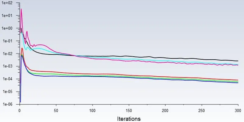
RESIDUALS:
DRAG FORCE:
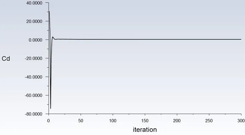
Drag Value:

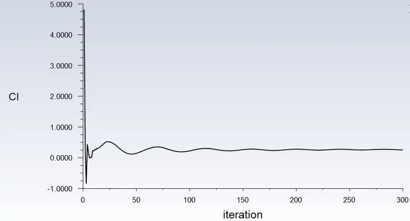
LIFT FORCE:
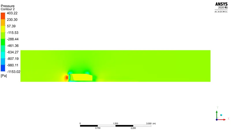
PRESSURE CONTOUR:
VELOCITY CONTOUR:
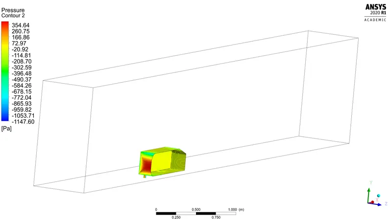
PRESSURE CONTOUR ON AHMED BODY :
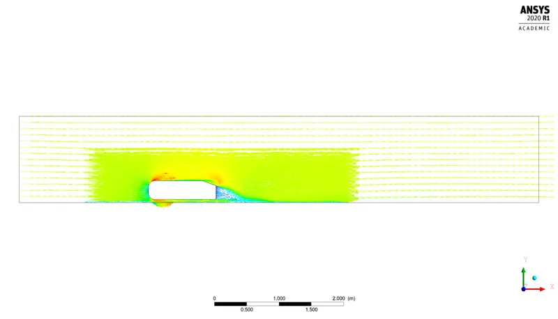
VELOCITY VECTOR PLOT :
GRID INDEPENDANCY TEST:
CASE 1:
Element size : 0.045m
Cell Count : 305309
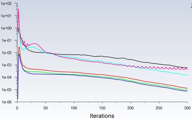
RESIDUAL:
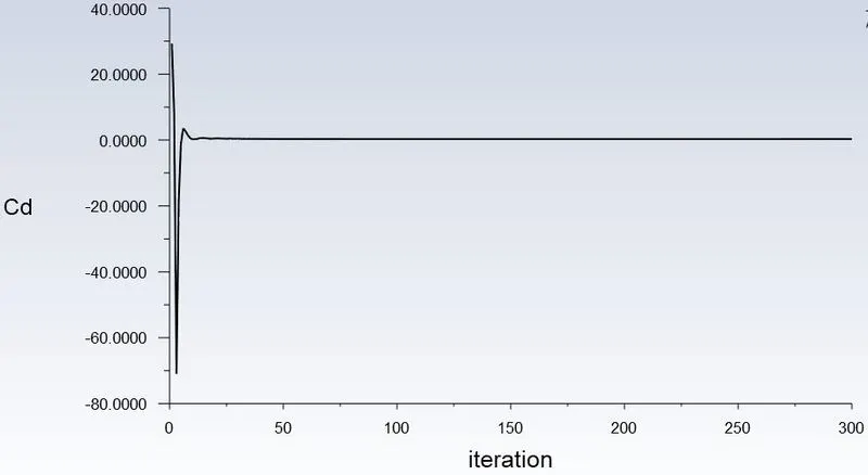
DRAG FORCE :
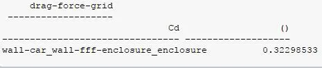
Drag value:
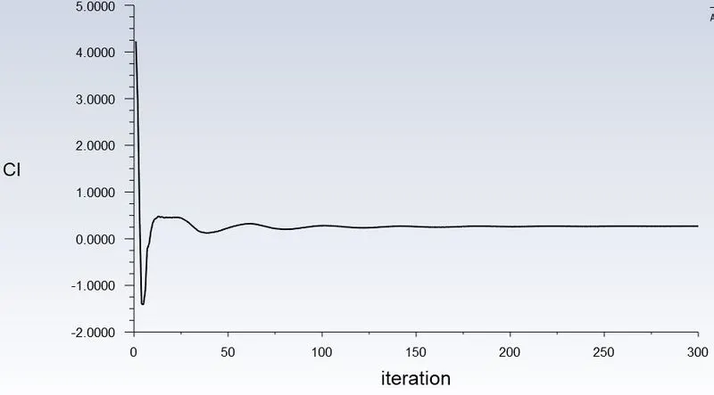
LIFT FORCE :
PRESSURE CONTOUR :
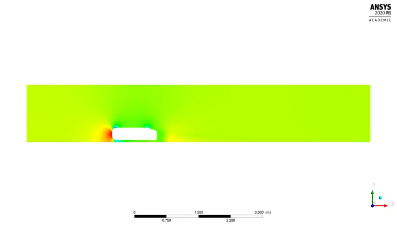
VELOCITY CONTOUR :
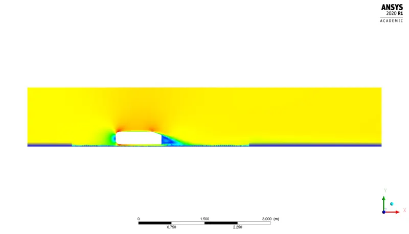
PRESSURE CONTOUR ON AHMED BODY :
VELOCITY VECTOR PLOT :
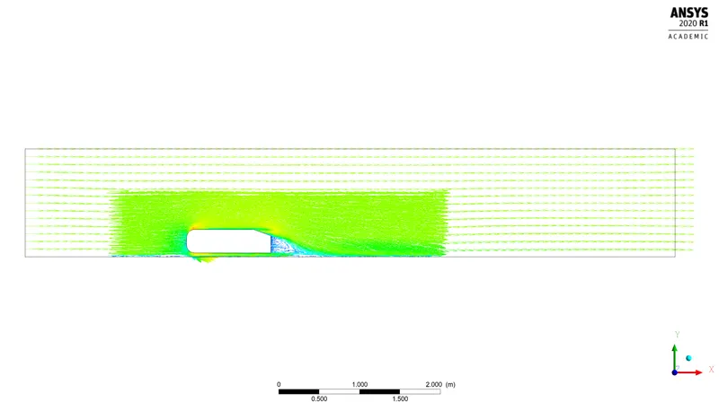
CASE 2 :
Element size : 0.06m
Cell Count : 246769
RESIDUAL :
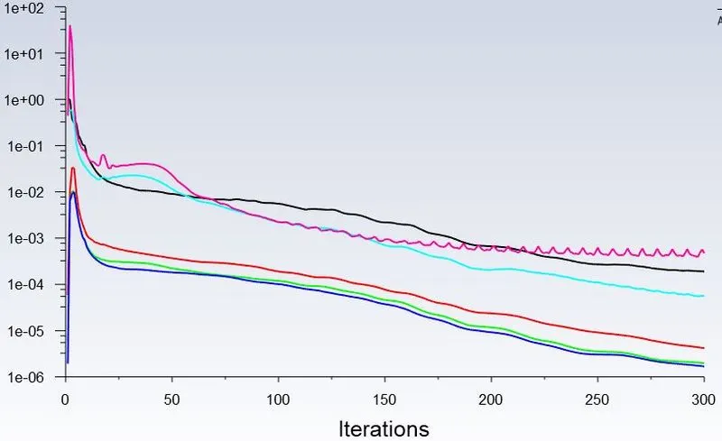
DRAG FORCE :
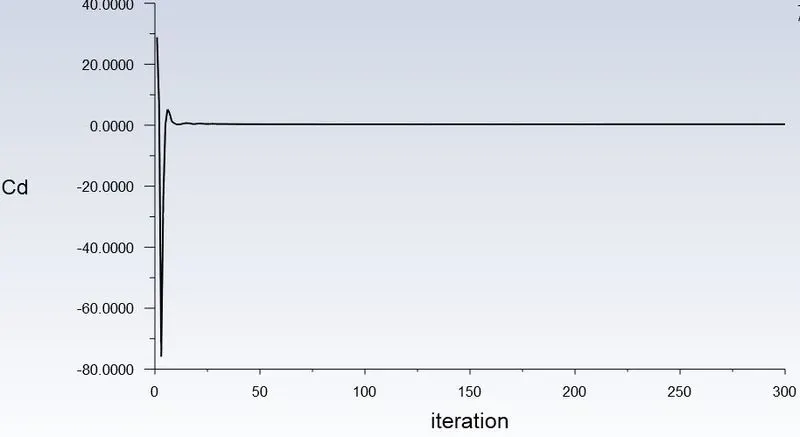
Drag value :

LIFT FORCE :
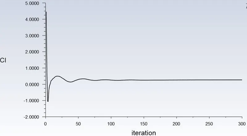
PRESSURE CONTOUR :
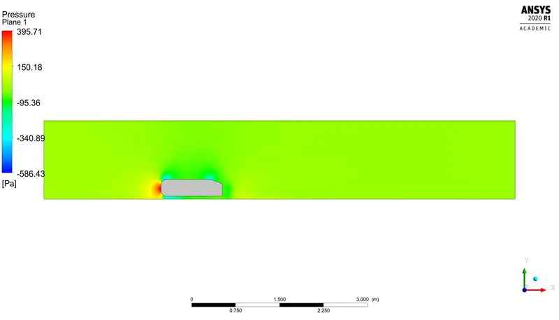
VELOCITY CONTOUR :
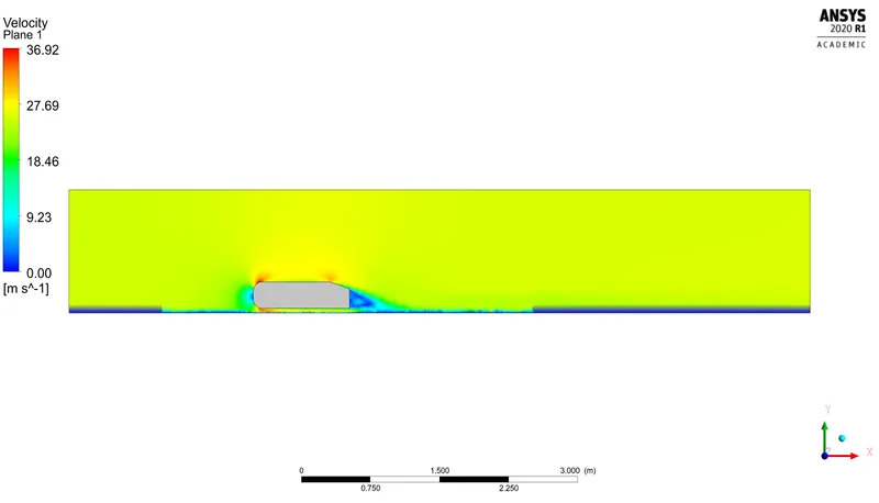
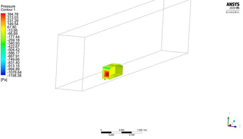
PRESSURE CONTOUR ON AHMED BODY :
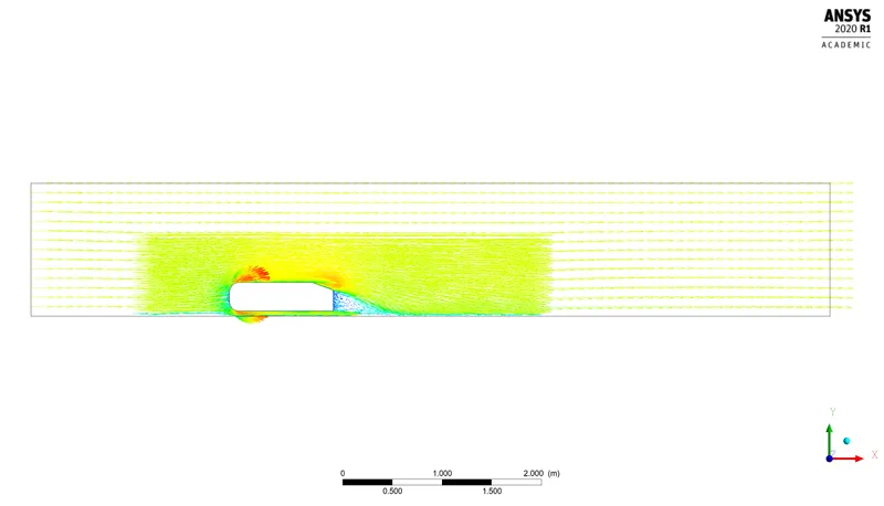
VELOCITY VECTOR PLOT :
RESULTS :
DRAG COEFFICIENT VALUE
| BODY SIZING ELEMENT SIZE in m | CELL COUNT | DRAG COEFFICIENT |
| 0.035 | 428658 | 0.3213 |
| 0.045 | 305309 | 0.3229 |
| 0.06 | 246769 | 0.3267 |
SIGNIFICANCE OF POINT OF SEPERATION:
The position at which boundary layer leaves the surface of a solid body is known as point of seperation.
It may occur with laminar flow or when boundary layer is turbulent.
Due to excessive momentum loss near the wall in boundary layer trying to move downstream against increasing pressure.
The limit between forward and reverse flow in the layer very close to the wall.
If there is a point of seperation, there must exist a point of inflection in the velocity profile..
This seperation point leads to boundary layer seperation.
REASON FOR NEGATIVE PRESSURE IN WAKE REGION:
Due to viscous losses, stagnation pressure in the wake is lower than stagnation pressure at front of the cylinder.However it has higher pressure than the fluid that is moving outside of the wake.
If the vehicle is moving along front,then force in wake is acting on back.
When vehicle velocity increases, pressure decreases.Thus pressure acts on -ve region.
Its due to continuous flow,separation of bubbles and effects on shear stress.To overcome these effects,pressure acts negative in a wake region.