Ahmed Body Challenge
Ahmed Body Challenge Objectives:
Q1. Describe Ahmed's body and its importance.
Q2. Explain the reason for the negative pressure in the wake region.
Q3. Explain the significance of the point of separation.
- Expected Results:
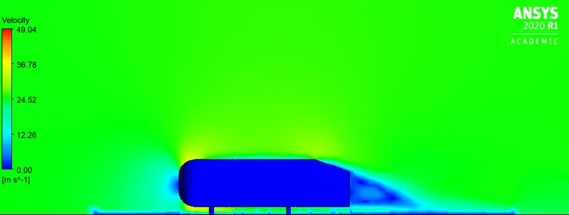
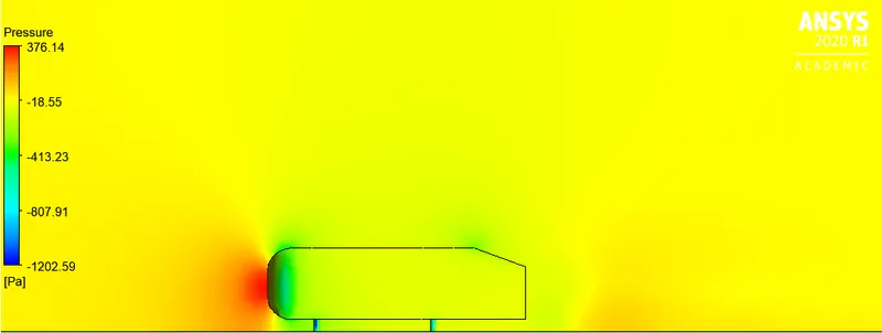
1. Velocity and pressure contours.
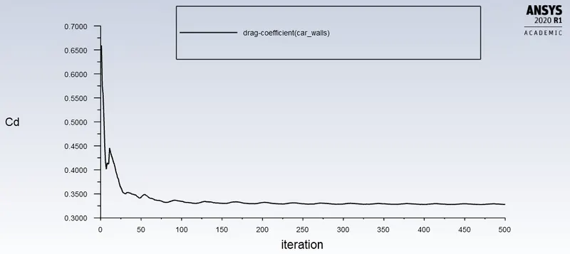
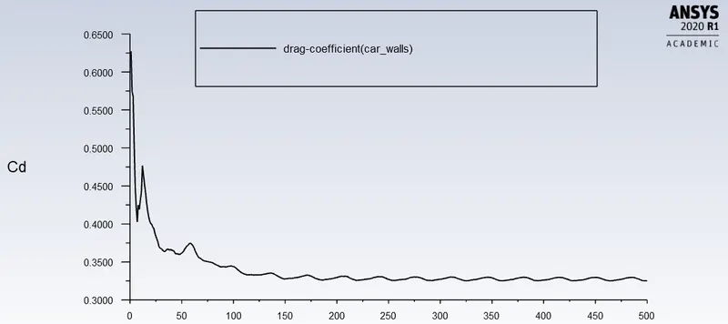
2. The drag coefficient plot for a refined case. (For velocity of 25m/sec, the drag coefficient should be around 0.33).
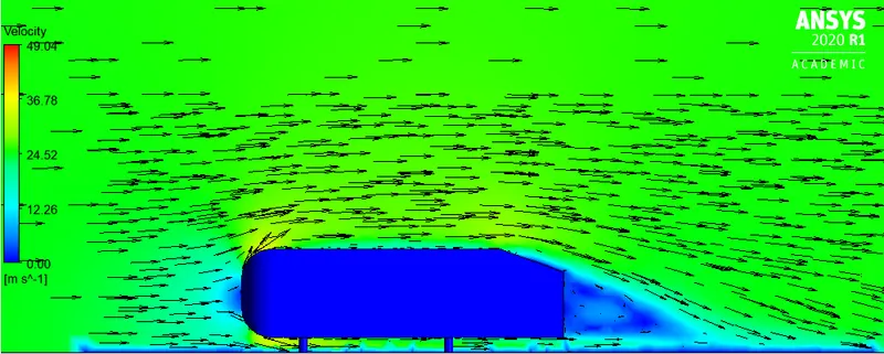
3. The vector plot clearly showing the wake region.
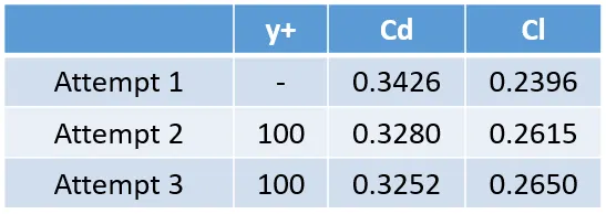
4. Perform the grid independency test and provide the values of drag and lift with each case.
Solution:
Ahmed body and its importance:
The Ahmed body is a generic car body (a simplified vehicle model). The airflow around the Ahmed body captures the essential flow features around an automobile and was first defined and characterized in the experimental work of Ahmed. Although it has a very simple shape, Ahmed body allows us to capture characteristic features that are relevant to bodies in the automobile industry.
This model is also used to describe the turbulent flow field around a car-like geometry. Once the numerical model in validated, it is used to design new models of the car.
Significance of the point of separation:
The presence of the fluid viscosity slows down the fluid particles very close to the solid surface and forms a thin slow-moving fluid layer called a boundary layer. The flow velocity is zero at the surface to satisfy the no-slip boundary condition. Inside the boundary layer, flow momentum is quite low since it experiences a strong viscous flow resistance. Therefore, the boundary layer flow is sensitive to the external pressure gradient (as the form of a pressure force acting upon fluid particles). In this case, the pressure force can assist the fluid movement and there is no flow retardation. However, if the pressure is increasing in the direction of the flow, an adverse pressure gradient condition exists. In addition to the presence of a strong viscous force, the fluid particles now have to move against the increasing pressure force. Therefore, the fluid particles could be stopped or reversed, causing the neighbouring particles to move away from the surface. This phenomenon is called the boundary layer separation.
Reason for the negative pressure in the wake region:
The wake is the region of disturbed flow (often turbulent) downstream of a solid body moving through a fluid, caused by the flow of the fluid around the body.
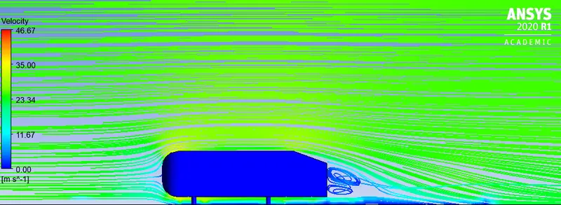
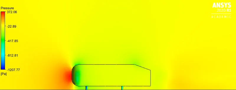
Fluid particles flow within the boundary layer around the Ahmed body. The pressure is maximum at the stagnation point and gradually decreases along certain region of front half of the Ahmed body. The flow stays attached in this favourable pressure region as expected. However, the pressure starts to increase in the rear of the Ahmed body and the particles now experience an adverse pressure gradient. Consequently, the flow separates from the surface and creating a highly turbulent region behind the cylinder called the wake. The pressure inside the wake region remains low as the flow separates and a net pressure force (pressure drag) is produced.
Grid Independence Test and it's significance:
A CFD simulation can never be trusted unless we check whether the result depends on the grid or not, or else we have any experimental data. The output result of a coarser mesh and finer mesh can neither be the same. So up to what extent, we need to vary the mesh to get the accepted level of tolerance, can be found out from Grid Independence test.
This is done by varying mesh size from coarse to fine and checking the output result of each mesh. When varying the mesh does not affect the result much then we can stop and select that minimum mesh size for our final solution attempt.
Geometry:
a) Ahmed Body Geometry:
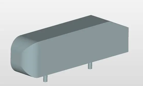
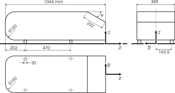
ATTEMPT 1:
b) Enclosures created around Ahmed body to capture fluid flow around it effectively:
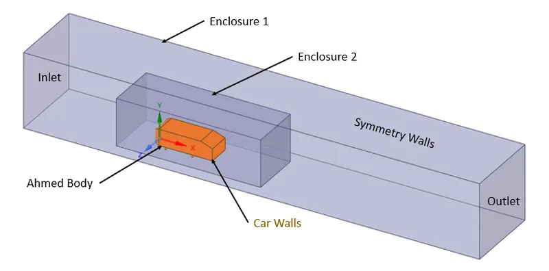
The Enclosure feature is a tool used to enclose the bodies of a model so that the material enclosing the bodies can be assigned to something such as a gas or fluid in the ANSYS Mechanical Application. The feature takes either all the bodies or selected bodies of the model as input, creates a frozen enclosure body around those bodies, and then cuts the bodies out of the enclosure.
The dimensions of the enclosures are as follows:
- Enclosure 1 (Main Enclosure):
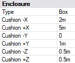
- Enclosure 2:
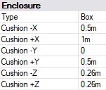
Enclosure 2 is created to have more refined mesh and to obtain better results.
Interference between enclosures is removed. Topology sharing enabled.
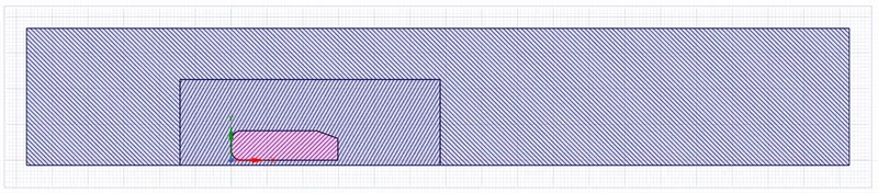
Grid dependency test is performed with multiple attempts (by refining mesh using local mesh refinement techniques), based on meshing size in order to achieve drag coefficient around 0.33.
ATTEMPT 1:
> Meshing Details:
- Meshing details of Enclosure 1:
- Mesh Type: Hexa
- Element Size: 100 mm
- Method: Multizone
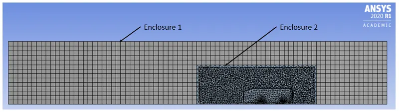
- Meshing details of Enclosure 2:
- Mesh Type: Tetrahedral
- Element Size: 50 mm
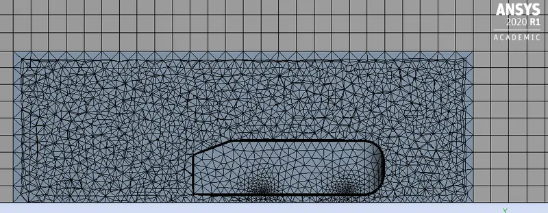
- Inflation Layers around Ahmed Body Walls (Car Walls) and its Legs:
- Number of Layers: 5
- Growth Rate: 1.2
- First Layer Height: 5 mm
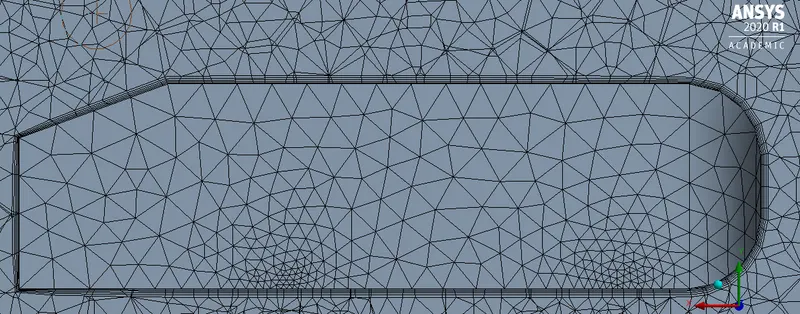
In initial attempt, y+ value is not considered to get an overview of its effects and importance accordingly. The consideration of y+ value and its importance is dealt in further attempts.
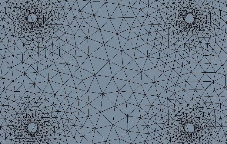
- Face Sizing around Legs of Ahmed Body:
- Element Size: 5 mm
- Growth Rate: 1.2
- Mesh Statistics:
- Nodes: 55292
- Elements: 178164
> Setup:
- Solver: Pressure Based
- Algorithm: SIMPLE (Semi Implicit Method for Pressure Linked Equations)
- Time: Steady
- Fluid: Air
- Viscous Model: K-Epsilon
- K-Epsilon Model: Realizable
- Near Wall Treatment: Standard Wall Functions
- Boundary Conditions:
- Inlet Velocity: 25 m/s
> Solution:
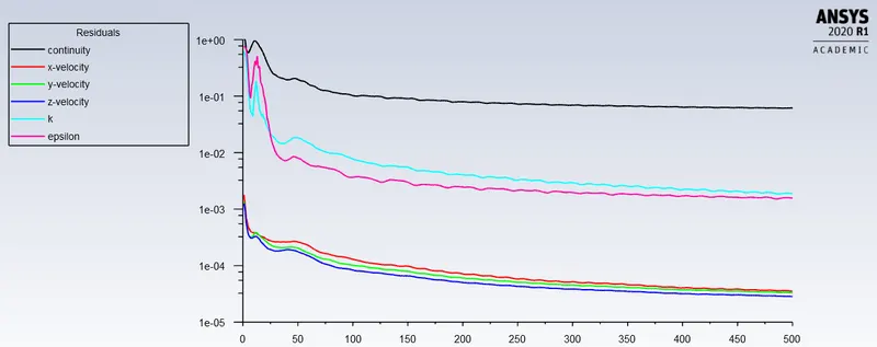
- Residuals Plot:
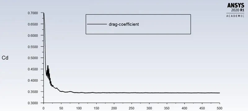
- Drag Coefficient Plot:
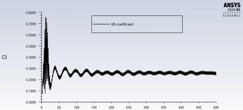
- Lift Coefficient Plot:
-Cd and Cl Values Obtained from attempt 1:
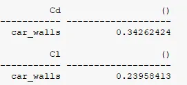
The Cd value (0.343) obtained in first attempt is near to 0.33. Hence, this case needs to be further revised to obtain Cd value close to 0.33 as mentioned in objective.
> Results:
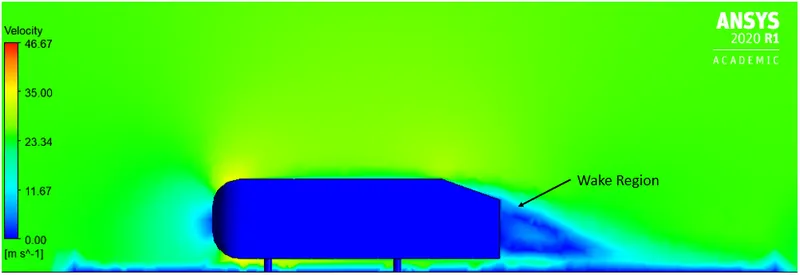
- Velocity Contour Plot:
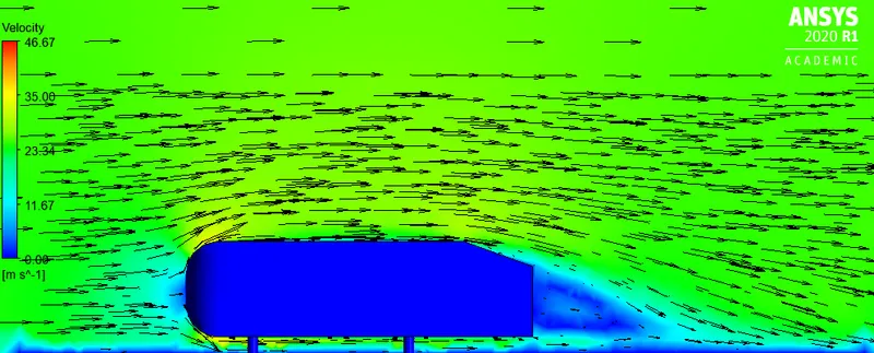
- Velocity Contour Plot with Vectors:
- Velocity Contour Plot with Streamlines:
- Pressure Contour Plot:
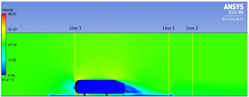
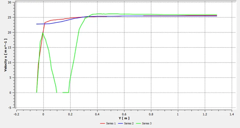
- Velocity at certain Vertical Stations using Line Probes:
ATTEMPT 2:
> Details of Refined Mesh:
Meshing in second attempt is refined further to obtain better drag coefficient value (0.33) compared to previous attempt.
Since academic version of Ansys is being used here, it is limited to cases with only 512000 cells.

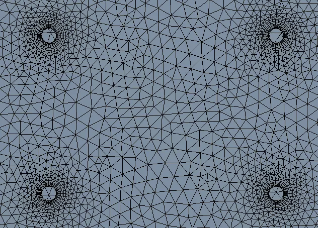
- Meshing details of Enclosure 1:
- Mesh Type: Hexa
- Element Size: 60 mm
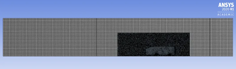
- Meshing details of Enclosure 2:
- Mesh Type: Tetrahedral
- Element Size: 40 mm
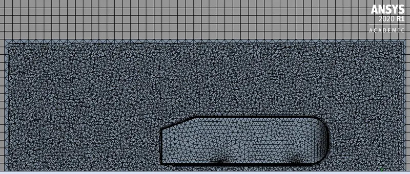
- Calculating First Layer Height or Near Wall Distance for given y+ :
Wall functions are useful in telling the solver how to approach the solution near wall. These are used to predict near-wall results accurately even at coarse grids. There are multiple wall functions for each turbulence model, but the most basic is the standard wall function.
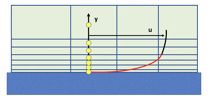
The y+ value is a non-dimensional term that can be used to understand how coarse or fine our grid needs to be. It is given by,
We know that, for K-Epsilon model and standard wall function Y+ value range is 30 < y+ < 300. Here, we are aiming for y+ = 100
We know that,
y+ = `(rhou_tauy)/mu`
`=>`100 = `(1.225xx1.0103xxy)/(1.8xx10^-5)`
`=>`y = 1.45 mm
- Inflation Layers around Ahmed Body Walls (Car Walls) and its Legs:
- Number of Layers: 8
- Growth Rate: 1.2
- First Layer Height: 1.45 mm
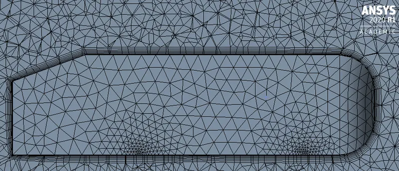
- Face Sizing around Legs of Ahmed Body:
- Element Size: 3 mm
- Growth Rate: 1.2
- Mesh Statistics:
- Nodes: 159905
- Elements: 413862
> Setup:
- Solver: Pressure Based
- Algorithm: SIMPLE (Semi Implicit Method for Pressure Linked Equations)
- Time: Steady
- Fluid: Air
- Viscous Model: K-Epsilon
- K-Epsilon Model: Realizable
- Near Wall Treatment: Standard Wall Functions
- Boundary Conditions:
- Inlet Velocity: 25 m/s
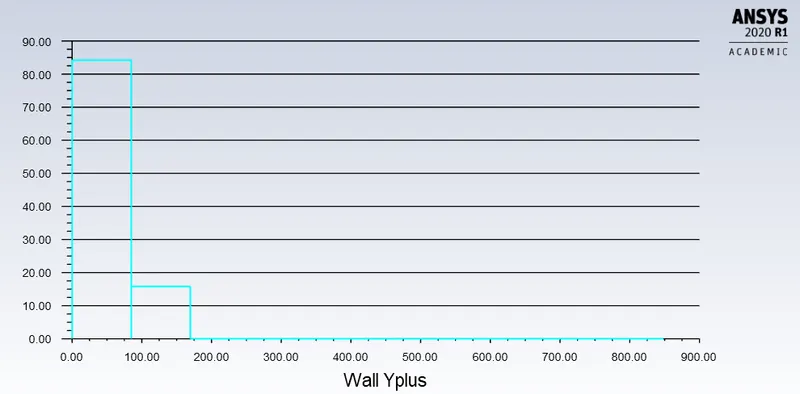
- Histogram of Wall y+ :
- Wall y+ VS X-Direction Vector Along Air Flow Over Ahmed Body:
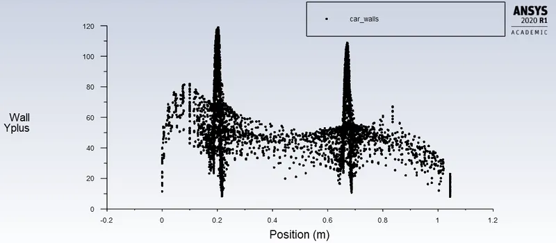
Y-Axis Function: Turbulence, Wall y+
X-Axis Function: Vector Direction in Air Flow
From the plot, it can be observed that most of the Ahmed Bod Wall (Car Wall) Cells lies in y+ range 30-300 for K-Epsilon, Standard Wall Function.
> Solution:
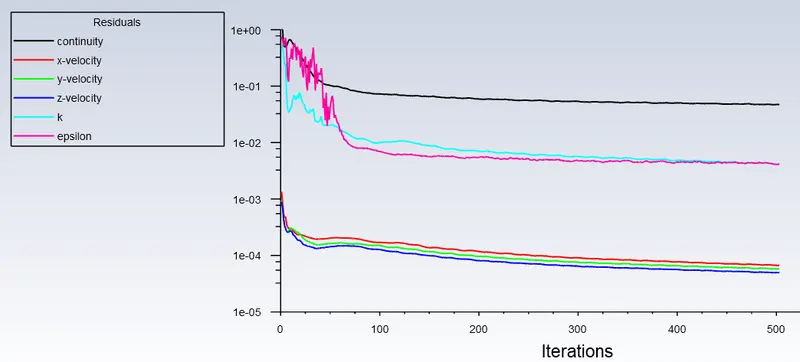
- Residuals Plot:
- Drag Coefficient Plot:
- Lift Coefficient Plot:
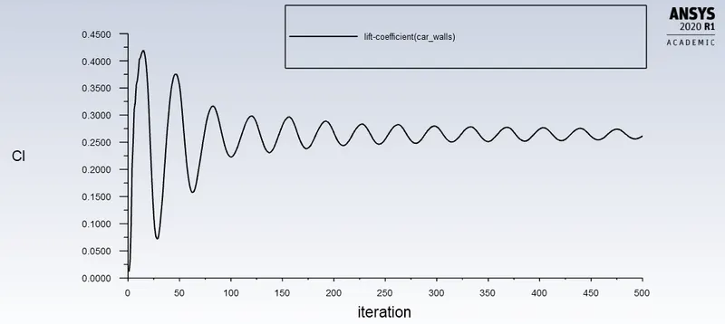
-Cd and Cl Values Obtained from attempt 2:
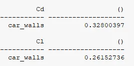
The Cd value (0.3280) obtained in second attempt is almost equal to Cd value (0.33) given in objective.
> Results:
- Velocity Contour Plot:
- Animation:
- Velocity Contour Plot with Vectors:
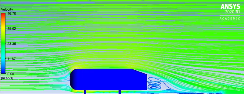
- Velocity Contour Plot with Streamlines:
- Pressure Contour Plot:
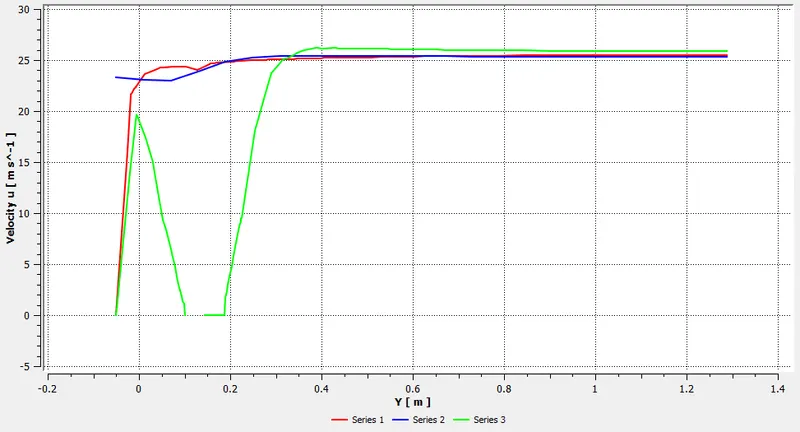
- Velocity at certain Vertical Stations using Line Probes:
ATTEMPT 3:
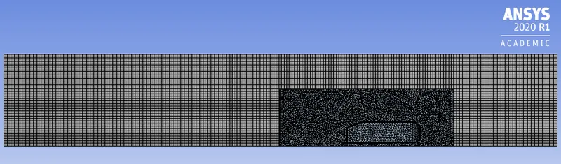
> Meshing Details:
Meshing in third attempt is refined further to obtain better drag coefficient value (close to 0.33) compared to previous attempt.
- Meshing details of Enclosure 1:
- Mesh Type: Hexa
- Element Size: 55 mm
- Method: Multizone
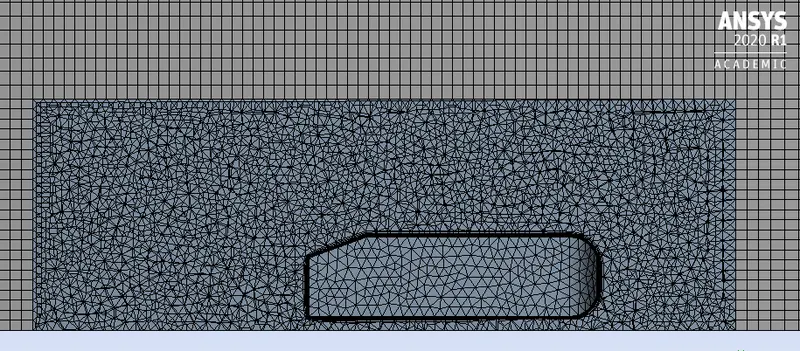
- Meshing details of Enclosure 2:
- Mesh Type: Tetrahedral
- Element Size: 38 mm
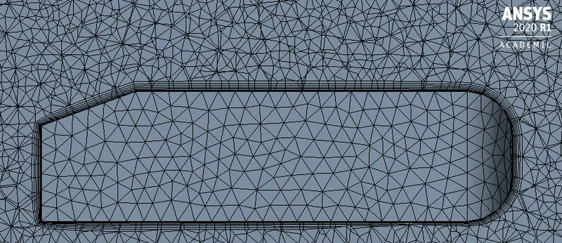
- Inflation Layers around Ahmed Body Walls (Car Walls) and its Legs:
- Number of Layers: 8
- Growth Rate: 1.2
- First Layer Height: 1.45 mm (Calculated based on y+ = 100, calculation shown in attempt 2)
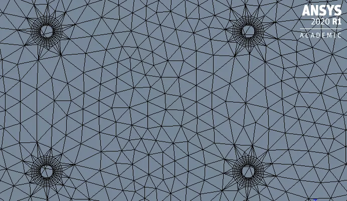
- Face Sizing around Legs of Ahmed Body:
- Element Size: 3 mm
- Growth Rate: 1.2
- Mesh Statistics:
- Nodes: 222104
- Elements: 500303
> Setup:
- Solver: Pressure Based
- Algorithm: SIMPLE (Semi Implicit Method for Pressure Linked Equations)
- Time: Steady
- Fluid: Air
- Viscous Model: K-Epsilon
- K-Epsilon Model: Realizable
- Near Wall Treatment: Standard Wall Functions
- Boundary Conditions:
- Inlet Velocity: 25 m/s
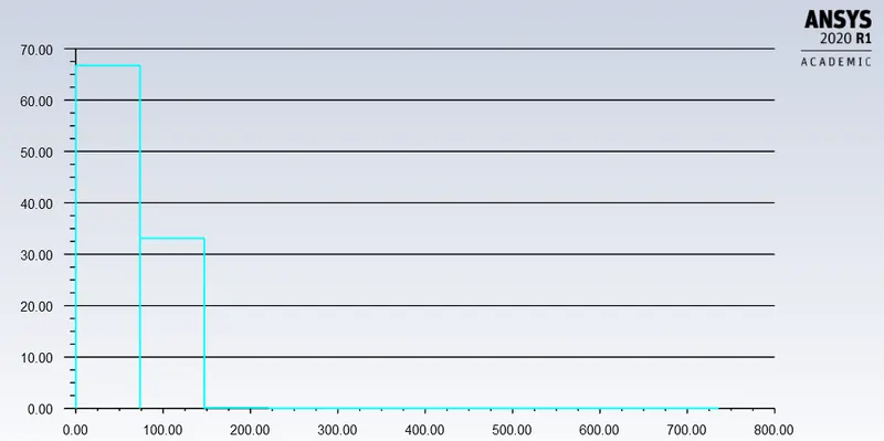
- Histogram of Wall y+ :
- Wall y+ VS X-Direction Vector Along Air Flow Over Ahmed Body
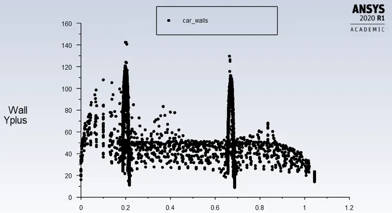
Y-Axis Function: Turbulence, Wall y+
X-Axis Function: Vector Direction in Air Flow
From the plot, it can be seen that most of the Ahmed Bod Wall (Car Wall) Cells lies in y+ range 30-300 for K-Epsilon, Standard Wall Function, compared to attempt 2.
> Solution:
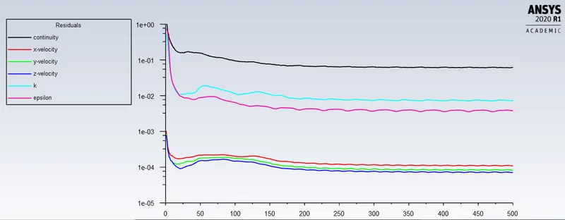
- Residuals Plot:
- Drag Coefficient Plot:
- Lift Coefficient Plot:
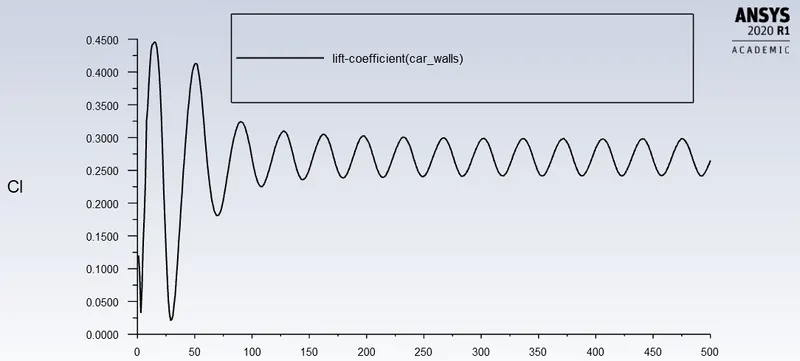
-Cd and Cl Values Obtained from attempt 3:
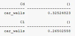
The Cd value (0.3252) obtained in second attempt is almost equal to Cd value (0.33) given in objective.
> Results:
- Velocity Contour Plot:
- Animation:
- Velocity Contour Plot with Vectors:
- Velocity Contour Plot with Streamlines:
- Pressure Contour Plot:
- Velocity at certain Vertical Stations using Line Probes:
Conclusion:
- The accuracy of Cd and Cl values are enhanced in attempt 2 by refining the mesh from coarser to finer. Accepted level of tolerance in Cd value is achieved from Grid Independence test.
- Formation of wake and recirculation regions can be seen from the velocity vector contours obtained in both attempts.
- Computation time in second attempt is comparatively higher than in attempt 1, as mesh is refined further. This might not be economical at certain cases.
- It is important to get into habit of checking y+ values as a part of normal post processing, so that one can make sure to fall in the valid range for the flow physics and turbulence model selection.
References:
[1] https://www.simscale.com/forum/t/what-is-y-yplus/82394
[2] https://www.simscale.com/docs/validation-cases/aerodynamics-flow-around-the-ahmed-body/
[3] https://skill-lync.com/knowledgebase/boundary-layer-y-plus-wall-functions-in-turbulent-flows-2