Advanced Sheet Metal Design Using NX Cad Challenge_7_ Metal bracket-II
Design of Metal Bracket-2 by using NX CAD
OBJECTIVE :- To design sheet metal bracket by using given dimension in NX cad software.
INTRODUCTION :-
Sheet metal is a metal forming process into thin pieces through various industrial processes like bending , punching, rolling, cutting, etc…
Here, I have converted to 3D metal Bracket from given 2D data.
DESIGN METHODOLAGY :-
| Select a new file in NX Cad |

| Select a sheet metal platform and saved with suitable name |
| Selected front plane to draw the sketch |
| Extruded the sketch by using contour flange command |
| One more sketch is created on front of the flange |
| As per previous sketch removed unwanted material by using normal cutout command |
| Additional to previous sketch added some holes |
| Normal cut out operation was done for the previous sketch |
| Corner treatment was done where ever required |
| Advanced flanges is created for top section of an object |
| Now unbend of an object was done to get a flat view |
| Oblong was created on the job at particular point, and cut out operation was done |
| Again advanced flange option was used for the previous sketch |
| Re bend operation was done from flat view |
| Now gusset was created at bend corners where ever required |
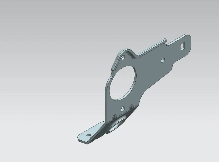
| As per the dimensions model is created and shown |
| Final touch up was given and finished the model |
DESCRIPTION :-
Normal cut out :-It is a command to cut material by projecting a sketch onto the model and then cutting perpendicular to the surfaces.
Break corner :-It is a command to round or chamfer sharp corners of a tab or flange.
Unbend :-It is a command used to flatten the sheet metal with respect to one flat sheet.
Rebend :-It is a command used to restore the unbend.
Hole :- It is a command is used to create a hole on the surface.
Gusset :-is a command which add a rib like structure between two sheet metal. It is also used for stiffening sheet metal.
Advanced flange :-It is a type of flange command which can create flange over curved edges also.
Contour flange :-It is a base feature by extruding a sketch along the vector or adds material by sweeping a sketch on edge.
IMAGES ;-
Front View :-
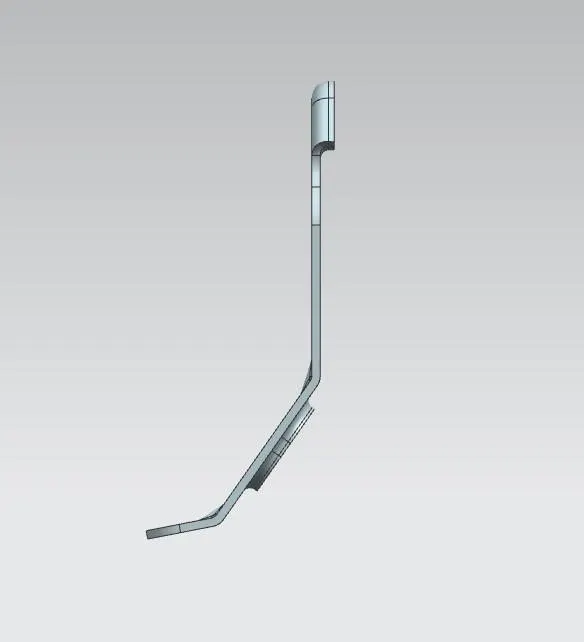
LEFT SIDE VIEW :-
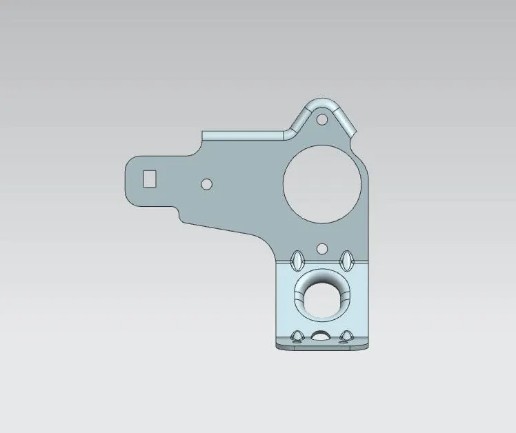
RIGHT SIDE VIEW :-
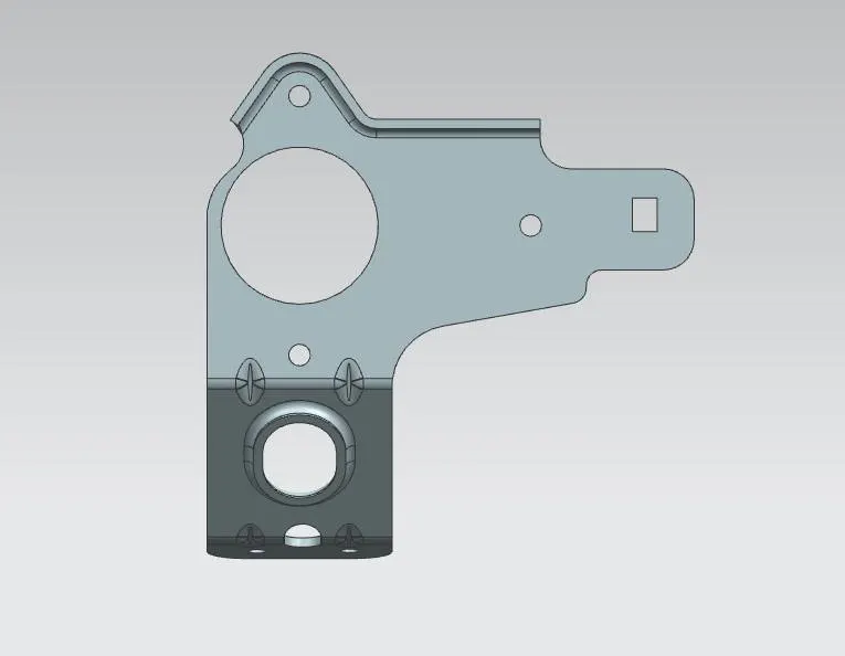
TOP VIEW ;-
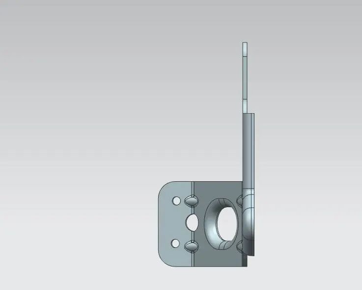
ISOMETRIC VIEW:-
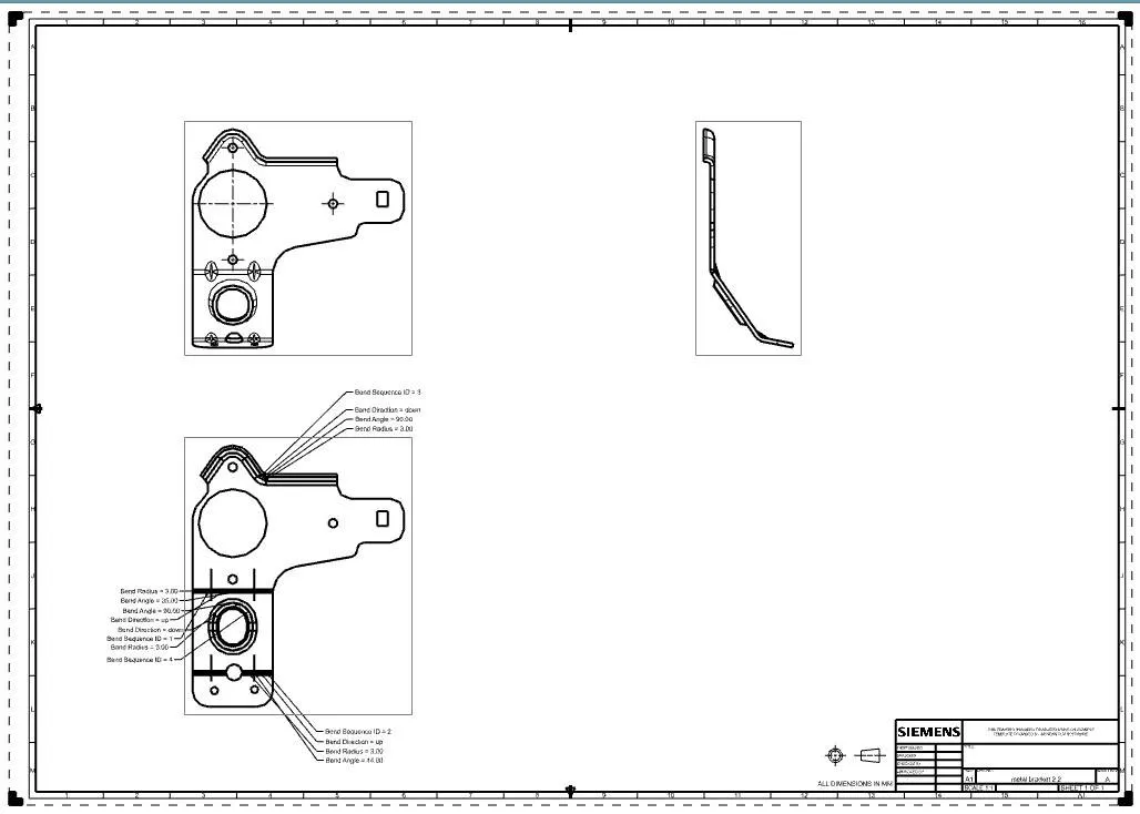
DRAWING SHEET :-
CONCLUSION :- The project help me in understanding the design methodology used to design such sheet metal part.
Knowledge of various tools of NX sheet metal work bench I got doing this work bench.