Advanced Sheet Metal Design Using NX Cad Challenge_7_ Metal bracket-II
DESIGNING OF METAL BRACKET
Aim: To design a metal bracket from the drawing given.
Brackets are the supportive structure in which something can be mounted rigidly and proper positioning.
Steps in design:
| SKETCHING IN X-PLANE |
| SKETCHING IN Y-PLANE |
| NORMAL CUTOUT |
| BREAK CORNERS |
| ADVANCED FLANGE ON TOP |
| SKETCHING OF CIRCLES TO CUTOUT |
| ADVANCED FLANGE IN THOSE CUTOUTS |
| GUSSETS ON BENDS |
S
we can get in to the design,
open NX and create a new window,
first of all we need to understand the drawings given.
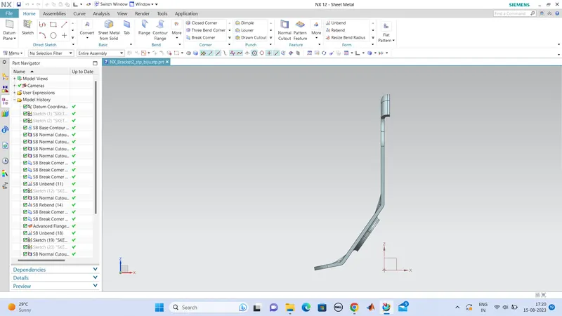
so first we need to sketch the drawing given in z-plane. and this bracket is a bend in shape . so we need to sketch the side view iin another plane and we can make a flange from the secong sketch and cut out the unwanted portions from the primary sketch.
so we can sketch another in x-plane with the proper dimentions.
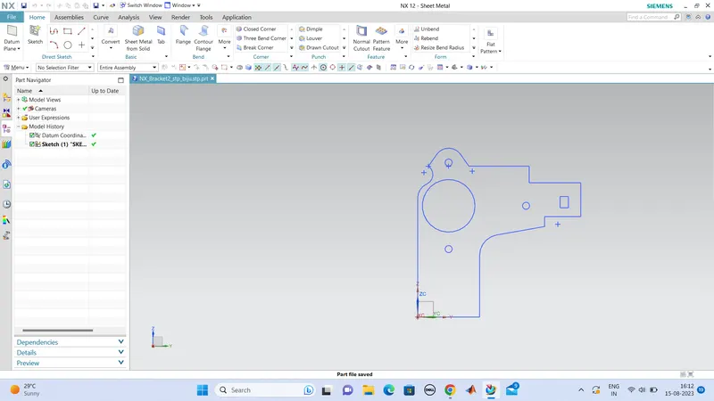
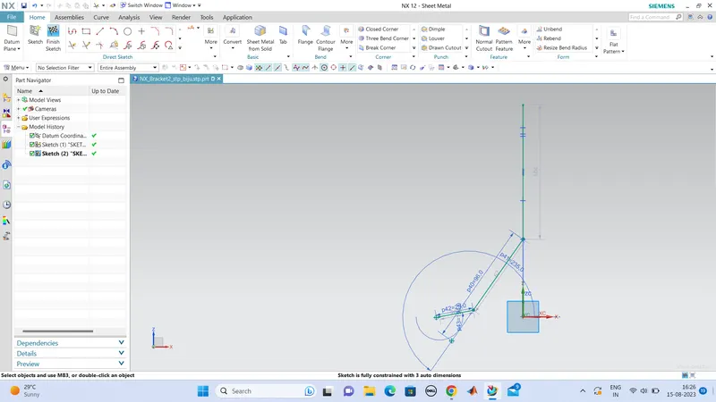
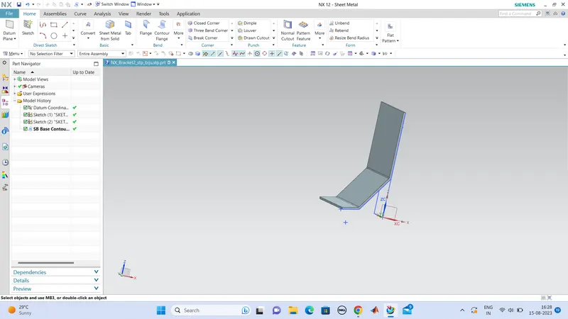
now we can make contour flange on this secong sketch up to a width of 158mm, and we can cut out the unwanted portions using 'normal cutout'.
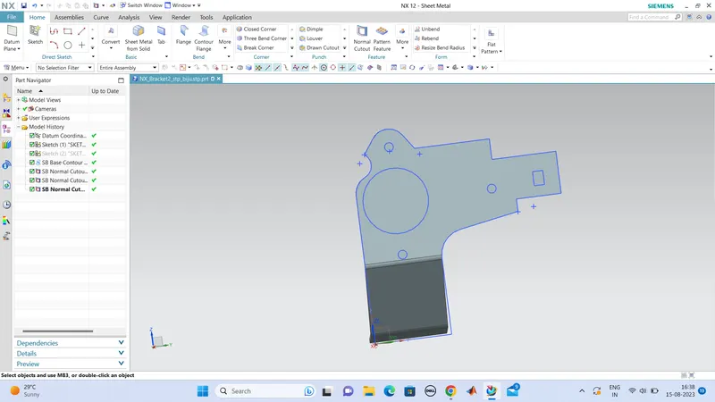
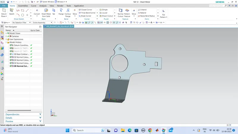
next we can unbend this sheetmetal and add more cutouts in the bottom portion.
and do the break corners with the given parameters.
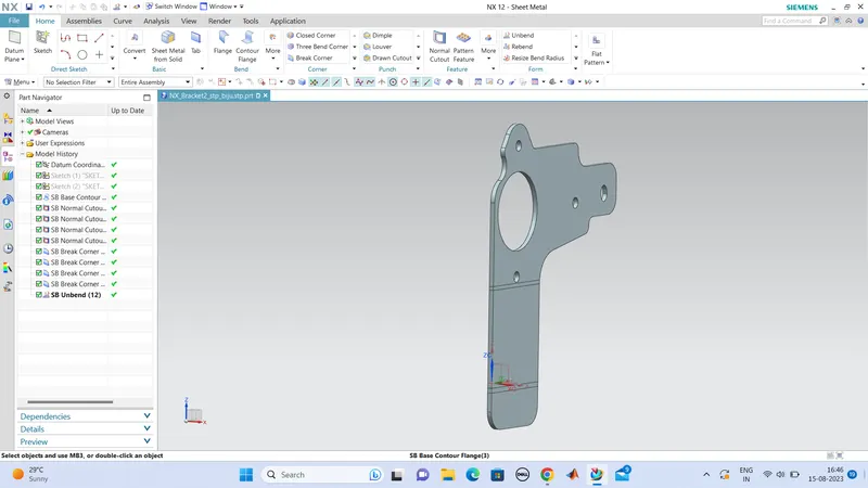
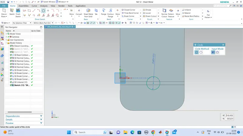
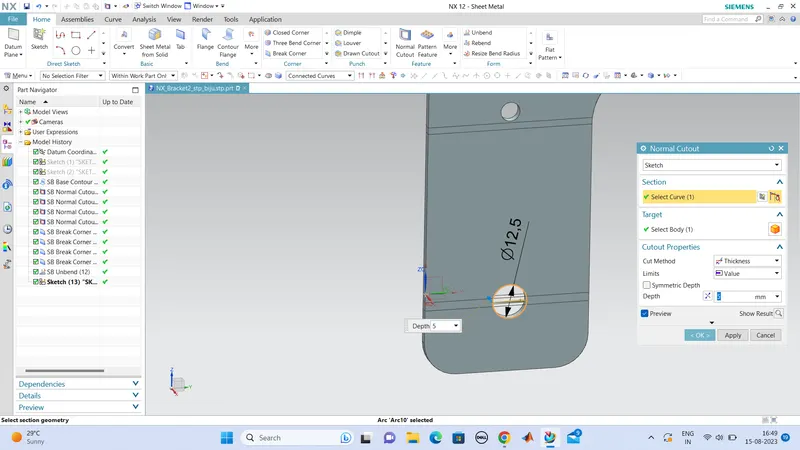
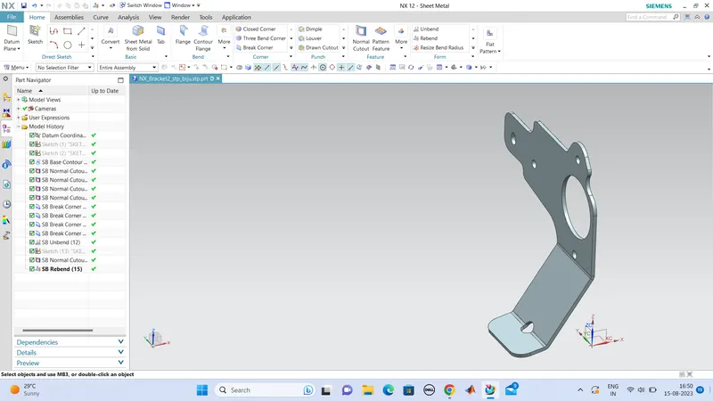
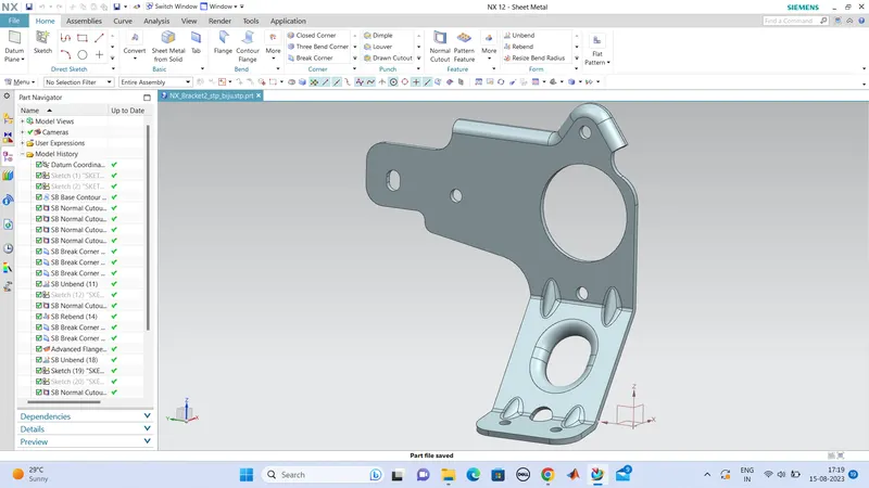
Next we can do advanved flange methos in the portion of curves, which means in the top portions we can make a advanced flange methos to make a flange of depth 5mm.
next we can do one more cutout,
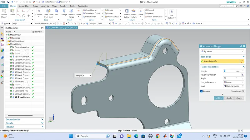
unbend this to make more cutouts.
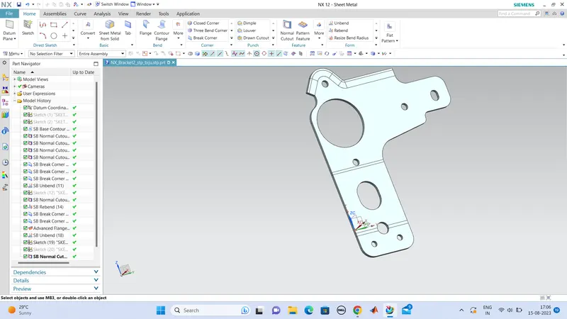
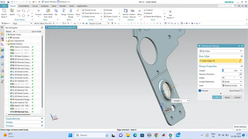
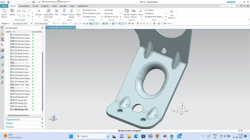
we can make this oval shaped cut out to a advanced flange up to a depth of 4mm.
so the cutouts are created and we can rebend this part to the original shape.
next we can make some gussets in the bend area, with round profile of 6mm width,
CONCLUTION:
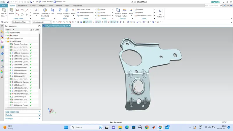
Hence the design is thus completed with the given drawings and looks good.