Advanced Sheet Metal Design Using NX Cad Challenge_7_ Metal bracket-II
TITLE : Advanced Sheet Metal Design Using NX Cad - Metal bracket-II
OBJECTIVE –
- Understanding Advanced sheet metal design.
- Modelling a Metal Bracket in sheet metal workbench from 2D drawing.
- Using advanced sheet metal features to design Metal Bracket.
INTRODUCTION –
The sheet metal application provides an environment for the design of sheet metal parts used in Machinery, Automotive, Aerospace, Marines, etc. Sheet metal is a metal such as aluminium, brass, titanium, nickel, tin, and copper processed into thin flat pieces like foils, leaves, and plates.
Sheet metals are a valuable asset to industries and low volume production. Many industries are adopting the concept of Design For Manufacturability, or more commonly known as DFM. In sheet metal design industries, DFM helps avoid technical errors in the design process to improve the manufacturing lead times based on the sheet metal thickness chart and preceding calculations.
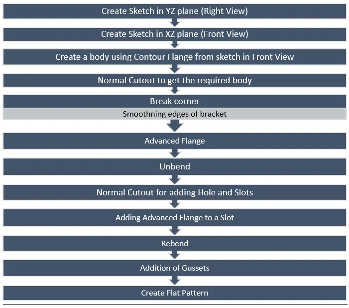
DESIGN METHODOLOGY / APPROACH –
DESIGN DESCRIPTION –
MODEL NAME – SM_BRACKET-II
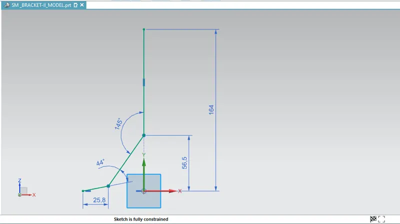
SKETCH – (YZ PLANE)
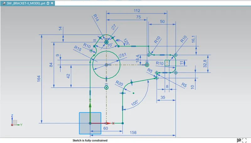
SKETCH – (XZ PLANE)
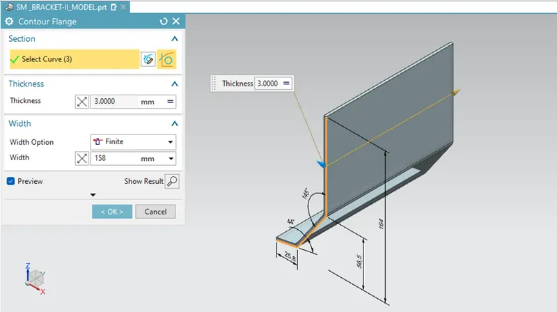
CONTOUR FLANGE –
Creates a base feature by extruding a sketch along a vector.
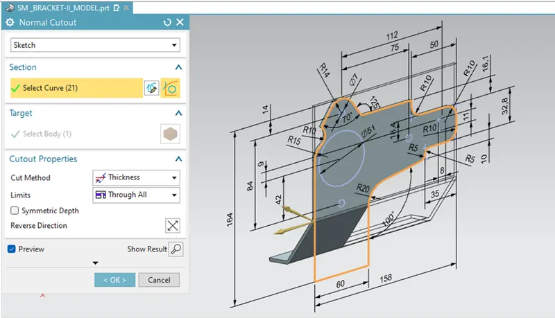
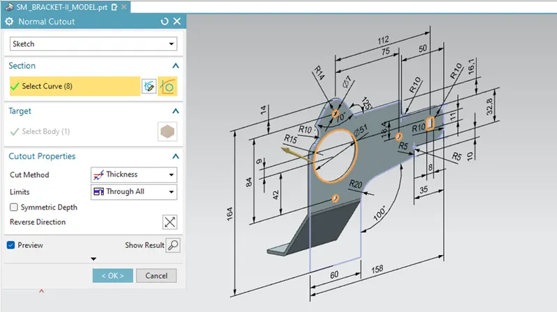
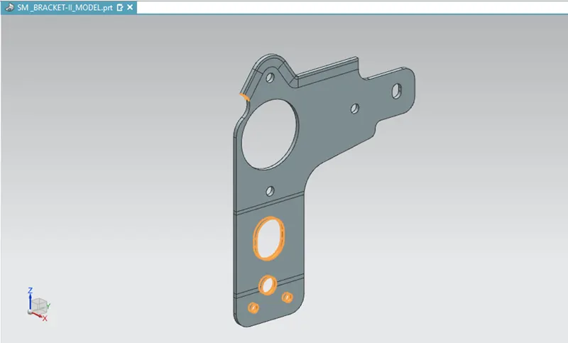
NORMAL CUTOUT –
Cuts material by projecting a sketch on to the model and then cutting perpendicular to the faces intersected by the projection.
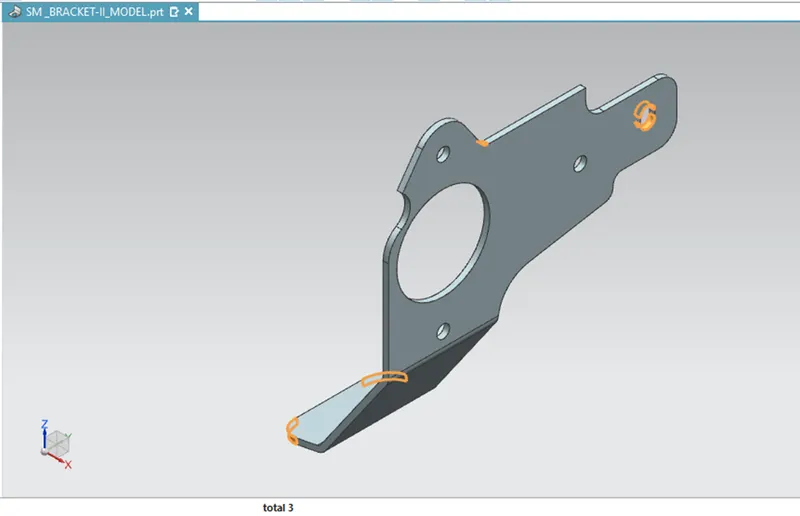
BREAK_CORNER –
Rounds or chamfers a sharp corner of a TAB or FLANGE.
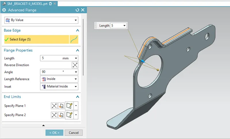
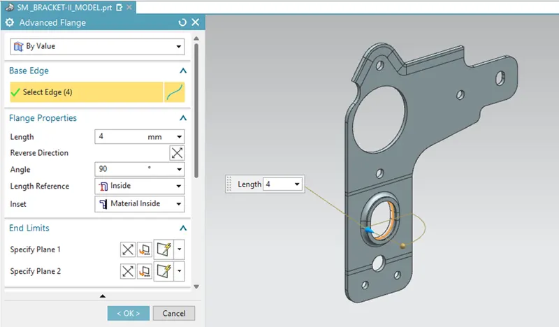
ADVANCED FLANGE –
Adds a flange along an edge using a bend angle or a reference face. The edge and reference face can be curved.
UNBEND –
Flattens a bend and the material adjacent to the bends.
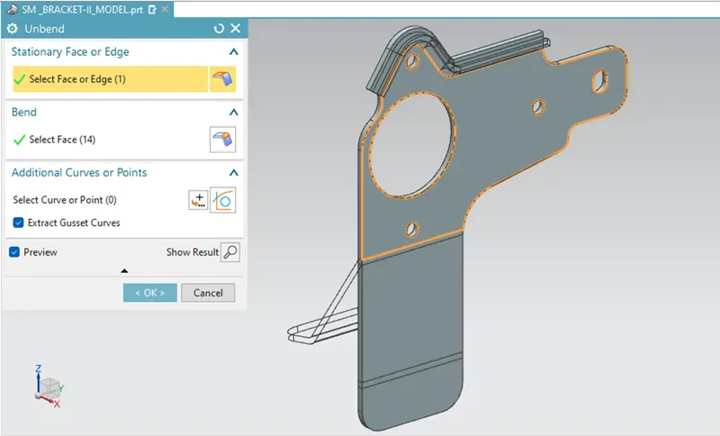
NORMAL CUTOUT – ( addition oh holes and slots )
ADVANCED FLANGE – ( for Slot )
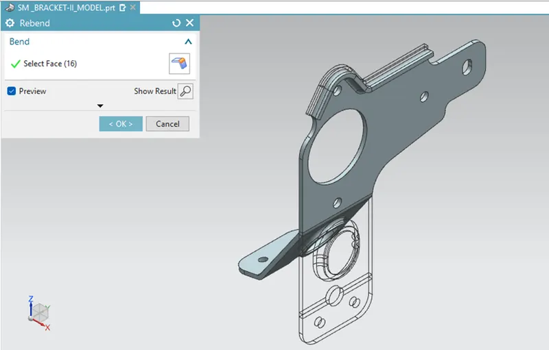
REBEND –
Restores an unbend feature to its previous bent state along with any features added after the unbend feature.
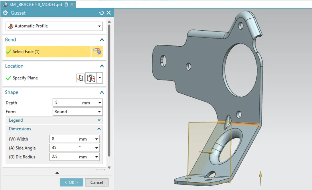
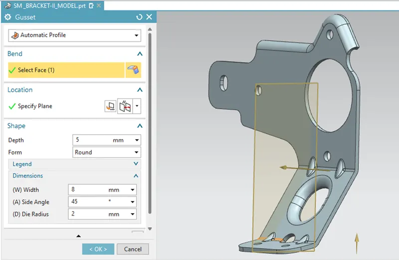
GUSSETS –
Creates a stiffening gusset on the part.
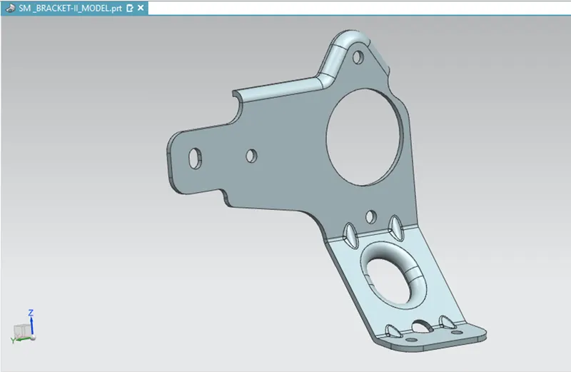
FINAL MODEL –
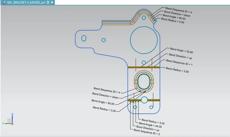
FLAT PATTERN –
Creates a flat pattern feature from the formed sheet metal part.
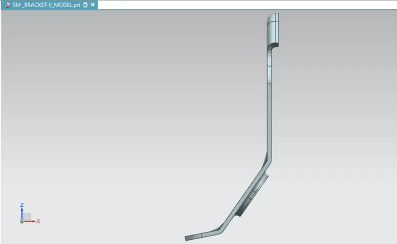
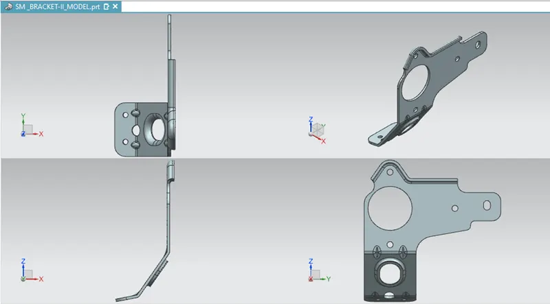
ORIENTATION VIEW – FRONT
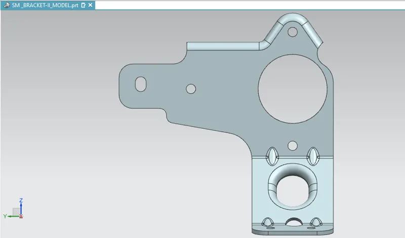
ORIENTATION VIEW – LEFT
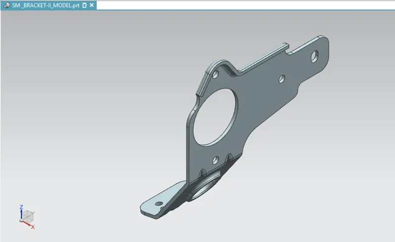
ORIENTATION VIEW – ISOMETRIC
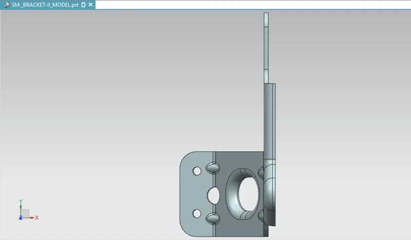
ORIENTATION VIEW – TOP
FOUR VIEW LAYOUT –
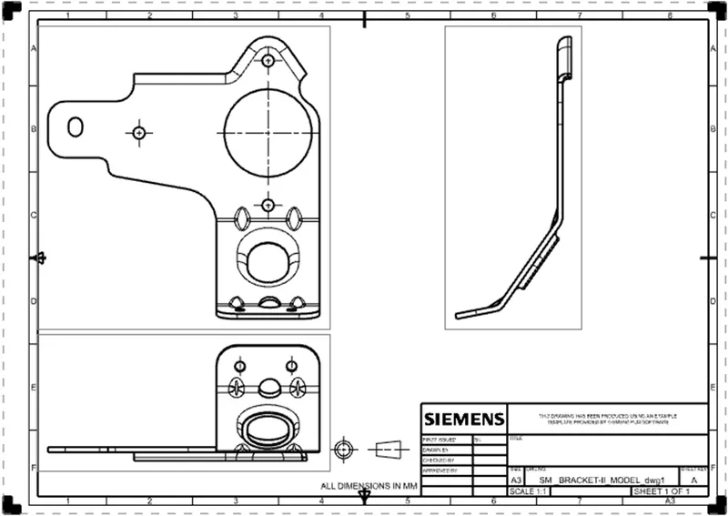
DRAWING SHEET –
CONCLUSION –
- Modelling of Metal Bracket on SiemensNX sheet metal workbench.
- Creation of sheet metal bracket from a 2D drawing.
- Advanced sheet metal features addition to create the metal bracket.
==========================================================