Advanced Sheet Metal Design Using NX Cad Challenge_7_ Metal bracket-II
Title of the Project: DESIGN and MODELLING of SHEET METAL BRACKET-2 BY USING SHEETMETAL APPLICATION in NX-12.
Objective:
To design a sheet metal bracket-2 in NX-12, you'll need to use the Sheetmetal application and its various features like Contour flange, Normal Cut-out, Break corner, Unbend, Bead, Re-bend, Hole, Advanced flange, and Gusset.
we'll start by creating a new sheet metal part file and importing the drawing of the bracket as a reference. Then, you'll use the features to create the flange, add cutouts and holes, break corners, add raised features like beads, and re-bend the flange if needed.
The Advanced flange feature is useful for more complex flanges, and the Gusset feature can be used to add additional support. By mastering these features, you'll be able to design and model sheet metal brackets in NX-12 with ease.
Introduction: -
Sheet metal Design and Fabrication: -
Sheet metal fabrication is a manufacturing process that involves transforming metal sheets into finished parts by using various techniques such as cutting, stamping, punching, and bending. These techniques are used to shape the metal sheet according to the desired design specifications and dimensions.
To fabricate sheet metal parts, 3D CAD files are first created and then converted into machine code that controls the fabrication machinery. This precise control allows for the creation of high-quality, accurate parts that meet the design specifications.
Sheet metal parts are known for their strength and durability, which makes them ideal for use in end-use applications such as chassis. However, the cost of fabricating sheet metal parts can be high due to the initial setup and material costs. Therefore, they are most cost-effective for use in low-volume prototypes and high-volume production runs.
Design Methodology / Approach:
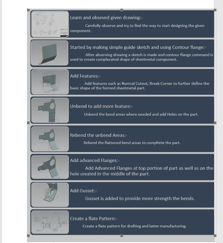
Designing the Sheet Metal Bracket:-
- Contour Flange– In Siemens nx sheet metal contour flange command used to create a base feature by extruding a sketch along a vector, or adds material by sweeping a sketch along an edge or chain of edge.
- Normal Cutout– Normal Cutout command extract volumes from sheet metal by using sheet metal production principles. Cutting faces will be perpendicular to the sheet metal surface.
- Break Corner– This feature is used to smoothen the harmful corner of the sheet or to give an attractive look to the part.
- Unbend– This feature is used to flatten the sheet metal part for further design operations.
- Rebend– Rebend feature is used to get the original bend shape after performing forming operations like a dimple, bead.
- Advanced Flange– This command is used to add a flange along an edge using a bend angle or a reference face. The edge and reference face can be curved. This command is useful when we want to create non-linear flanges, or when we work with sheet metal support structures in complex assemblies. We can use existing geometry as a reference to define the flange dimensions.
- 7. Gusset– Gussets are stiffening features created across a bend to reinforce the sheet metal part.
- Flatt Pattern– This feature is used to create an instance of the flat shape and size of the sheet metal that required to create the final part.
Procedure:
- Sketch the drawing for the contour flange on XZ plane with a width of 158mm.
- Using normal cut-out remove unwanted material by checking the 2D drawing.
- Use break corners to give a smooth curve to the corners according to the 2D drawing available.
- Unbend the model and cut out the shapes needed in the model.
- Rebend the model.
- Use advanced flange and select the upper edge with a flange length of 5mm.
- Unbend the model again and give holes at the bottom of the part according to the drawing.
- Use normal cut-out by sketching the shape between two bends. Then use advance flange on the same sketch.
- Rebend the model and apply the gusset feature at the bend as shown in the drawing.
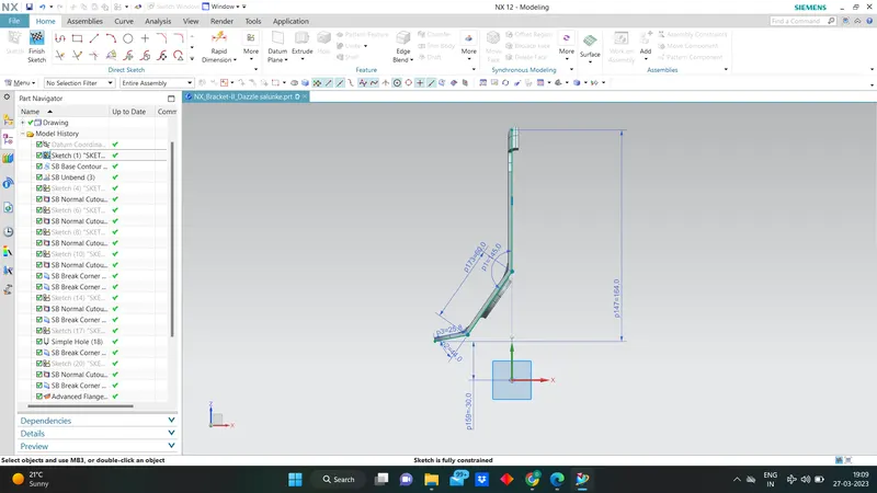
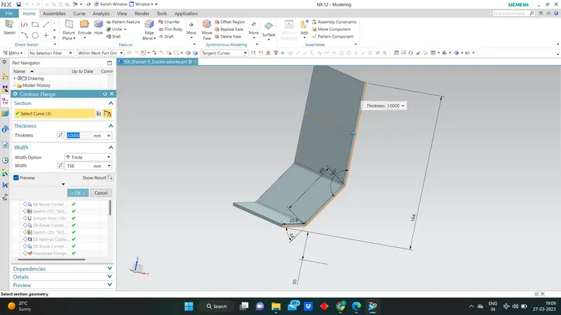
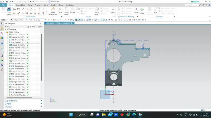
View:
Top view:
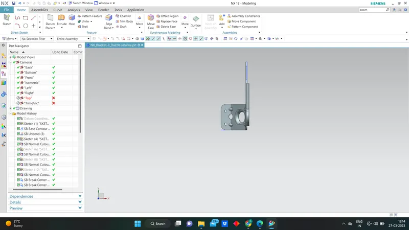
Side view:
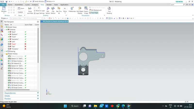
Front View:
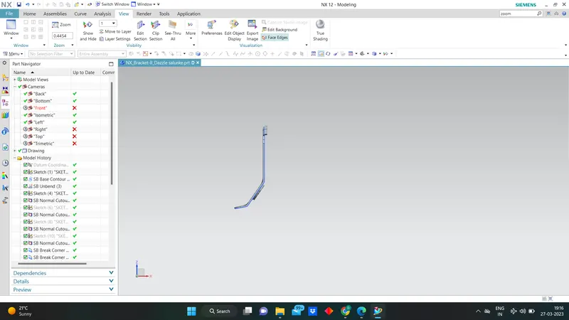
Bottom View:

Isometric View:
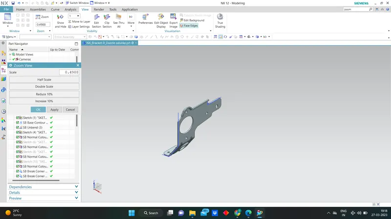
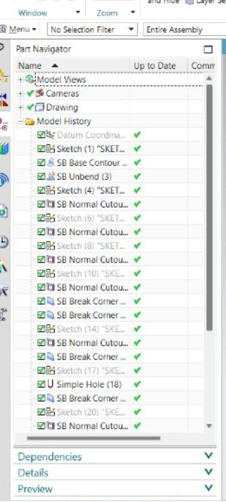
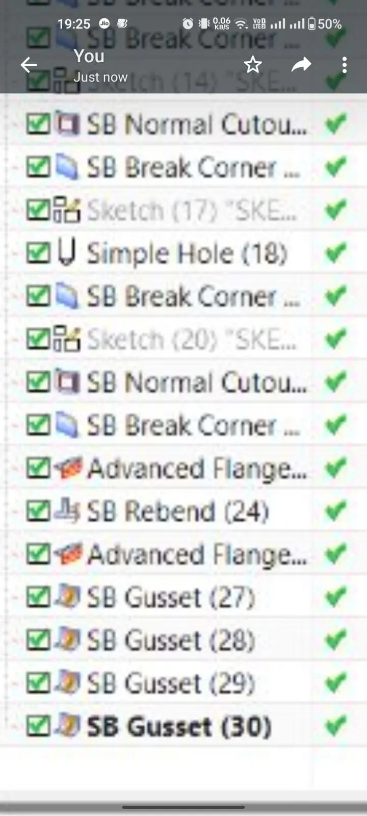
Part Navigator Tree:
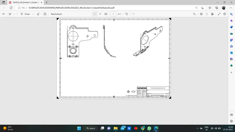
Drafting:
Conclusion:
The design of a sheet metal bracket was successfully achieved through the use of the NX Cad software, providing valuable insights into the advanced features of flanges and gussets.