Advanced Sheet Metal Design Using NX Cad Challenge_7_ Metal bracket-II
Metal bracket-II
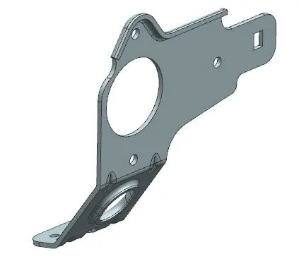
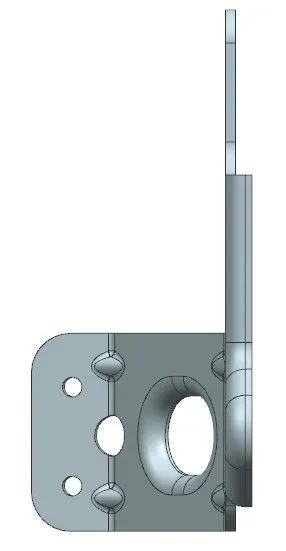
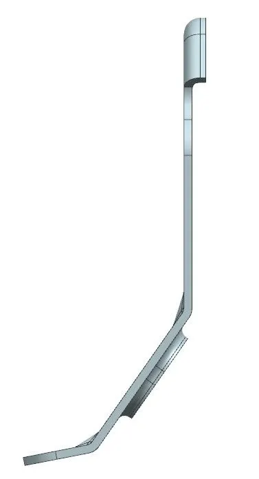
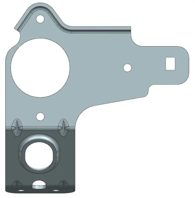
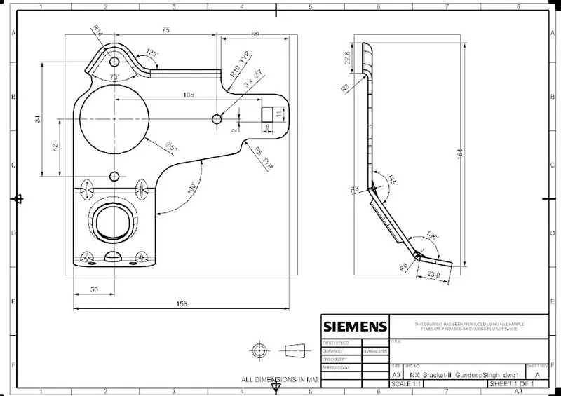
Objective :- To develop the given Bracket-II ie. Sheet Metal Component using Sheet Metal modelling tools applied throughout the modelling using NX.
Introduction:
NX CAD includes a specialized set of tools for designing sheet metal parts and assemblies. These tools allow users to quickly create and modify sheet metal parts, including features such as bends, flanges, and other common sheet metal operations.
Some of the key features of the sheet metal design tools in NX CAD include:
-
Bend definition: Users can create and edit bend lines, bend angles, and reliefs for sheet metal parts.
-
Flange and unfold: Users can create flanges and unfold sheet metal parts to create flat patterns for manufacturing.
-
Sheet metal gauge table: Users can define and apply sheet metal gauges to parts and assemblies.
-
Punch, laser and plasma: NX CAD allows user to define the punch, laser and plasma features on sheet metal parts.
-
Sheet metal simulation: Users can simulate the behavior of sheet metal parts under different loads and conditions, including the ability to predict springback and evaluate the effects of different manufacturing processes.
-
Sheet metal nesting: Users can optimize sheet metal parts for cutting and nesting to minimize material waste.
-
Manufacturing documentation: Users can create detailed drawings and documentation for sheet metal parts, including flat patterns, bend notes, and bend tables.
Overall, NX CAD provides a comprehensive set of tools for designing and manufacturing sheet metal parts, from initial design through to final production.
Design Methodology:
| New file selection in NX |

| Saved with Nx_Bracket-II_GundeepSingh |
| Selected YZ Plane and respective Sketch was performed |
| Selected XZ Plane and respective Sketch was performed |
| Conour flange with thickness 3mm and width 158mm is formed on the xz sketch |
| Normal cut is made on the sketch made on YZ at the required area |
| Sketch formed and performed normal cut out operation |
| Unbend the Sheetmetal by using unbend command |
| Added the holes and area as per required by using normal cut command |
| Rebend the component to original position |
| Corners were breaked with specific radius |
| Advance flange is performed on the top surface |
| Unbend the lower part and holes and cuts were made , further rebend the part |
| Advance flange is performed at the elliptical part |
| Gussets were made at the specific locations |
| Drafting Sheet with suitable Scale formed |
Description :
Sketch:- Allows to create and edit 2D geometry for use in 3D modeling.
Tab :- Create a tabular layout of items, such as dimensions or annotations, within a drawing.
Bend :- It is used to create a bend in a sheet metal part. It Can specify the bend angle, bend radius, and the location of the bend on the sheet metal part.
Flange :- It is used to create a flange on a sheet metal part. A flange is a projecting flat surface or rim used for strengthening or attaching to another object
UNBEND :- It is used to remove a bend from a sheet metal part.It can be used to change the shape of a bent sheet metal part back to its original flat state.
HOLE :- It is used to create holes in a solid or sheet metal part.
BEAD :- It is a raised ridge or protrusion on a sheet metal surface, often used to provide strength or to improve the appearance of a part.
REBEND :- It can be used to make changes to a bend after it has already been created, such as to correct an error or to make design changes.
Gussets: Gussets are used in sheet metal to strengthen a flange instead of giving a weld.
CONCLUSION
Hence the bracket II sheet metal part is created using NX12 software.