Advanced Sheet Metal Design Using NX Cad Challenge_7_ Metal bracket-II
METAL BRACKET DESIGN USING NX
OBJECTIVE:
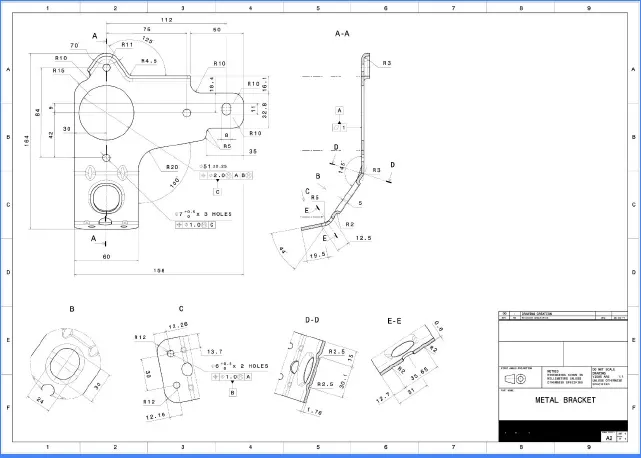
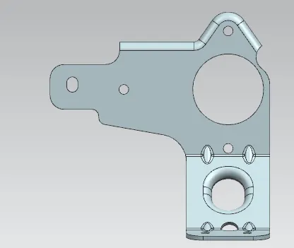
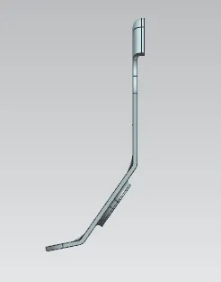
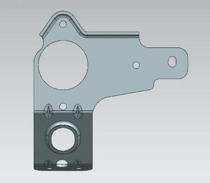
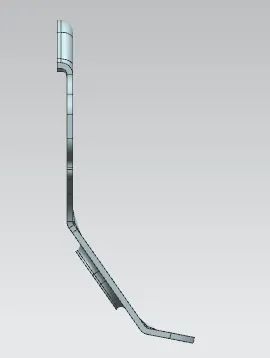
Design a Bracket from the given 2D drawing.
INTRODUCTION:
A bracket is an intermediate component for fixing one part to another. It is used to support the weight. Brackets vary widely in shape, here we are designing an L- shaped bracket.
The shape and dimension of your bracket will be determined by the shape of the item it is holding up but will also be affected by the load capabilities and the ease in manufacturing. Keep in mind that strength considerations of metal bracket design are not just functions of the material thickness but of the bracket shape. As a metal part, adding specific features to the bracket can improve strength dramatically. Below are shown 2 metal part designs, both are of the same thickness but the first part will be significantly stronger due to the gusset (small triangular piece) welded on the bracket. This is a nice feature for keeping the profile of the bracket small yet creating a strong bracket.
DESIGN METHODOLOGY
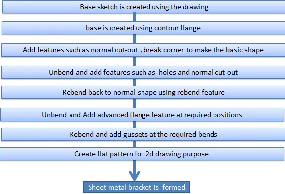
FEATURES
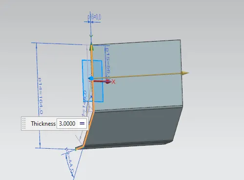
Contour Flange
In Siemens nx sheet metal contour flange command used to create a base feature by extruding a sketch along a vector, or adds material by sweeping a sketch along an edge or chain of edge.This feature creates a base feature by extruding a sketch along a vector, or adds material by sweeping a sketch along an edge or chain of edges.
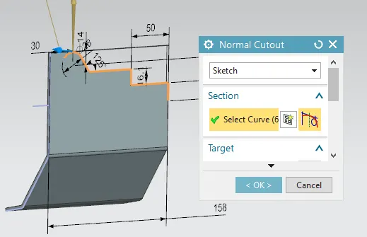
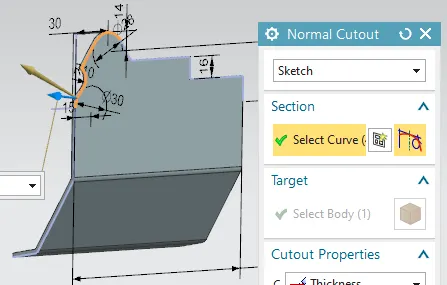
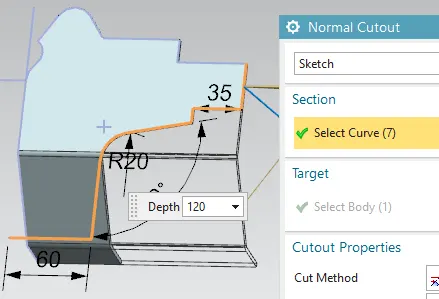
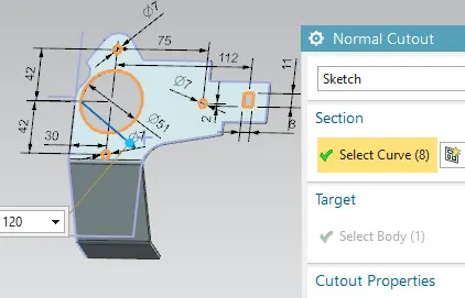
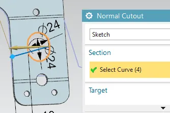
Normal Cutout
Normal Cutout command extract volumes from sheet metal by using sheet metal production principles. Cutting faces will be perpendicular to the sheet metal surface.
- Activate the “Normal Cutout” command.
- “Select Curve” in the “Section” tab will be highlighted automatically. Select a curve to extract.
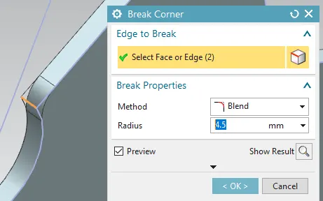
Break Corner
Break corner and chamfer tools are used to make some changes over sheet metal body. Rounds or chamfers a sharp corner of a tab or flange. Bend:completely formed with radius and creates smooth edges.
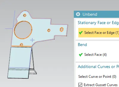
Unbend
This feature is used to flatten the sheet metal part for further design operations.
Rebend
Rebend feature is used to get the original bend shape after performing forming operations like a dimple, bead.
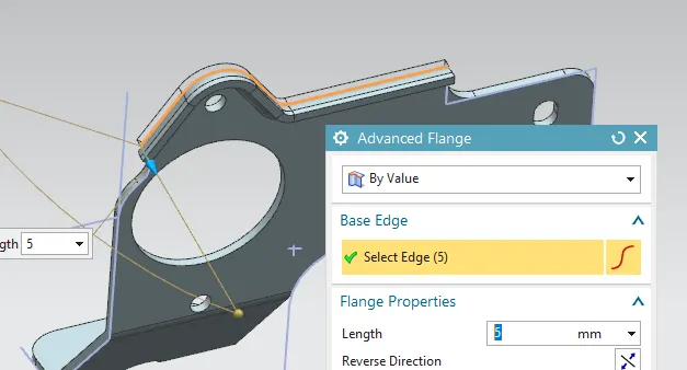
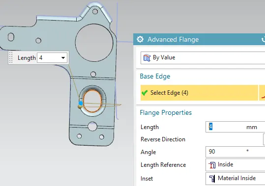
Advanced Flange
This command is used to add a flange along an edge using a bend angle or a reference face. The edge and reference face can be curved. This command is useful when we want to create non-linear flanges, or when we work with sheet metal support structures in complex assemblies. We can use existing geometry as a reference to define the flange dimensions.
Holes
It adds a hole to one or more solid bodies in a part or an asembly with options for counterbored, countersunk and threaded. Here six simple holes are created on the unbent surface with a diameter of 10mm. It can be used to make customized or standardized holes along with a defined point or path. The dept of the hole can be controlled.
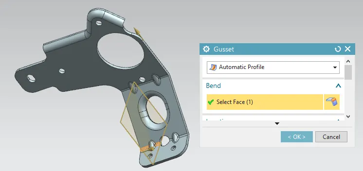
Gusset
Gussets are stiffening features created across a bend to reinforce the sheet metal part.
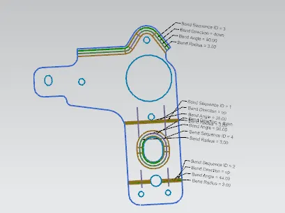
Flatt Pattern
It creates a flat pattern feature from the formed sheet metal part. The user chooses this command to create a flat view of the sheet metal after unbending all the sides and faces. This view can be used in drawing the flat pattern along with the bend radius and other dimensions.The flat pattern ensures the ability to cut the sheet metal out of the raw sheet metal plate. It removes the possible errors such as interference or collision within the same component.
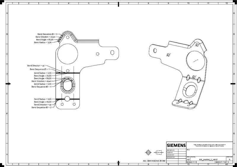
Drafting
After the design is complete, the execution or the manufacturing of the component requires a technical drawing of the component with the provided scale and with accuracy
2D DRAWING
STEPS
DRAWING SHEET
VIEWS
CONCLUSION
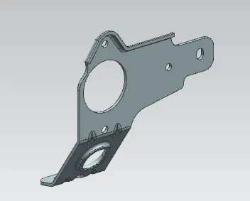
SHEET METAL BRACKET is designed and a draft is created using Siemens NX .