Advanced Sheet Metal Design Using NX Cad Challenge_7_ Metal bracket-II
METAL BRACKET
Objective :
The objective of this challenge is to design a metal bracket with mentioned tools and measurements in the Sheet metal Application of Siemens NX.
INTRODUCTION:
A bracket is an intermediate component for fixing one part to another. It is used to support the weight. Brackets vary widely in shape, here we are designing an L- shaped bracket. A Bracket is a component used to support load or any attachments to structural elements for heavy vehicles. It is subjected to different types of loading while the vehicle is in motion. One of the main common. loading is a static load that is assumed to be constant throughout the operation.
DESIGN METHODOLOGY:
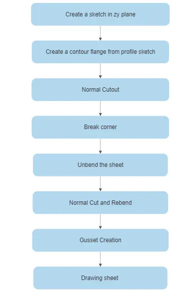
Description :
Sketch - Use the Sketch command to create a sketch and define its sketch plane, orientation, or origin. You can create a sketch on an edge, curve, datum plane, or planar face.
Contour Flange - Use the Contour Flange command to create a flange by extruding a sketch along a vector, or by sweeping a sketch along an edge or chain of edges. NX adds bends automatically using the default bend radius value. To use a different bend radius value, draw arcs in the section, or change the default bend radius value.
Normal Cutout - Use the Normal Cutout command to cut material by projecting a sketch onto the model and then cutting perpendicular to the faces intersected by the projection.
Break Corner - Use the Break Corner command to round or chamfer sharp corners of a tab or flange.
Advanced Flange - Use this command to add a flange along an edge using a bend angle or a reference face. The edge and reference face can be curved.
Hole - Use the Hole command to add the following types of hole features in a part or assembly.
Gusset - Use the gusset command to create a stiffening feature on a part.
Unbend - Use the Unbend command to unbend a portion of the part to construct cutout features, hole features, or deform features across a bend. You can later reform the bend to represent the true formed state of the model.
Rebend - Use the Rebend command to return an unbend feature to its previous bent state. Any features added after the unbend operation are properly repositioned during the rebend operation.
Images :
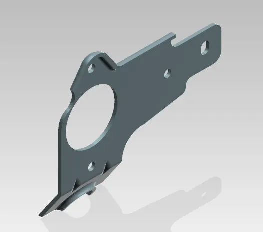
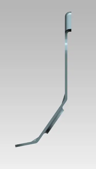
Isometric view
Top view
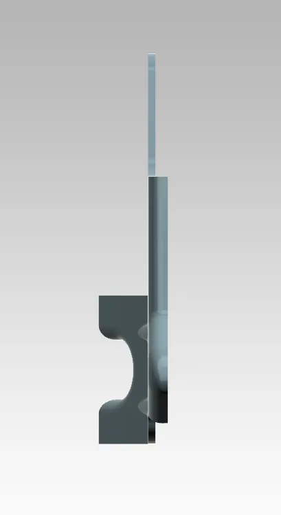
Side view
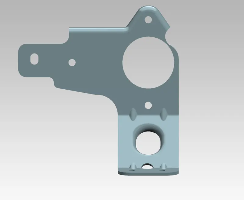
Front view
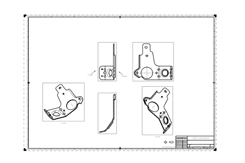
Drawing Sheet
CONCLUSION:
The sheet metal bracket is designed successfully using the NX Cad application. From this project, we understand advanced flange and gusset features.