Advanced Sheet Metal Design Using NX Cad Challenge_7_ Metal bracket-II
Design of Metal Bracket-2
Objective
To Design a sheet metal metal bracket by using NX CAD
Introduction
Sheet metal fabrication is the process of forming metal sheets to the desired shape using different manufacturing methods. The completion of a product usually comprises many steps from cutting and bending to surface treatment and assembling. Often times a variety of fabrication techniques can be used to achieve a similar end result. But the right choice is still existing, depending on the costs and needs.
There are many different industries that make use of sheet metal, whether it’s stainless steel, thin aluminum strips, or copper brass, here are a few industries that make frequent use of this material.
- Automotive
- Aerospace
- Construction
what is Bracket?
In short, a bracket is an intermediate component used to fix one thing (like a shelf) to another (like a wall). It may be thought of as a kind of fastener, but this is somewhat misleading: actual fasteners like screws are used to connect the bracket to the other parts. In addition to creating a connection between two parts, a bracket may provide support. Some brackets, such as gusset brackets, are designed with a diagonal section that reduces the strain on the bracket and allows it to support heavier loads.
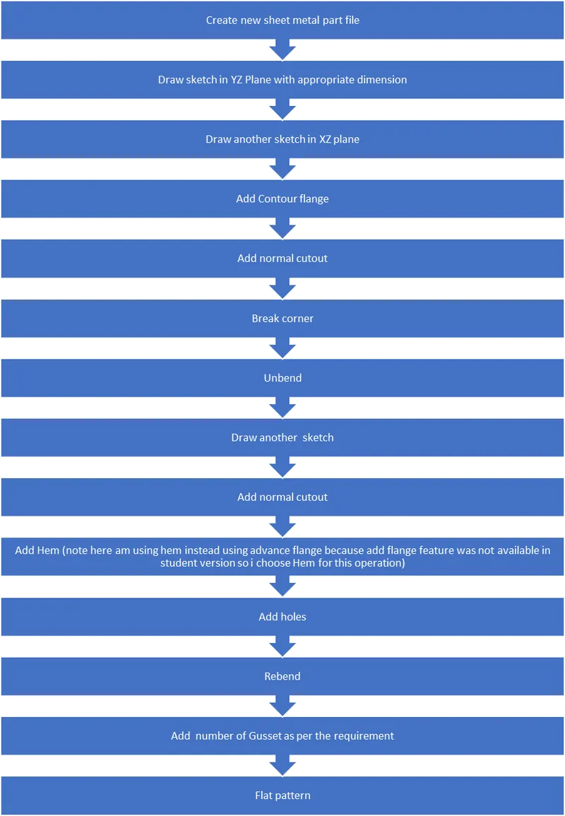
Design Methodology of Metal bracket
Features used
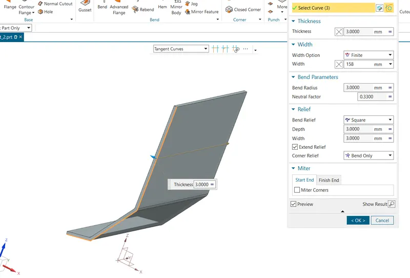
1. Contour flange -Creates main base flange or second flange by extruding sketch.
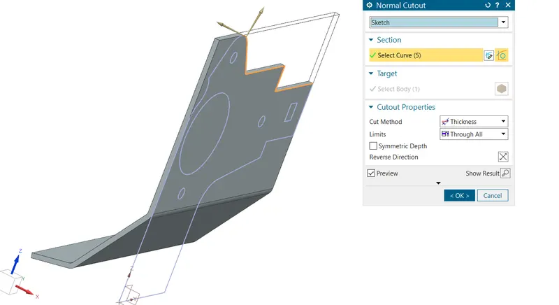
2. Normal cutout-Normal Cutout command extract volumes from sheet metal by using sheet metal production principles. Cutting faces will be perpendicular to the sheet metal surface.
3. Break corner-Break corner is used to provide a fillet type faster to the sharp corners of the sheet metal. it is used to provide safety as well as to relieve stress concentration.
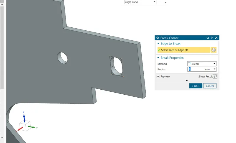
4. Unbend-Flattens the sheet model through selected bends
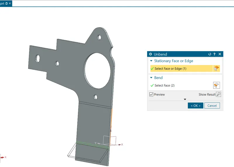
5. Rebend -Rebends, the unbent feature of the sheet metal model. It uses after the “Unbend” command If needed.
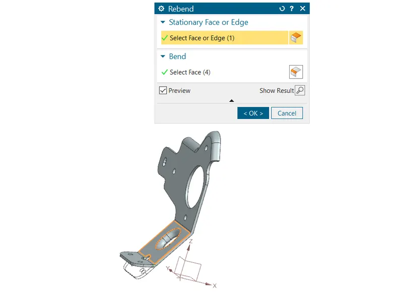
6. Hem -Modifies the model by folding the edge of a sheet metal flange over itself for the purpose of safe handling or to increase edge stiffness.
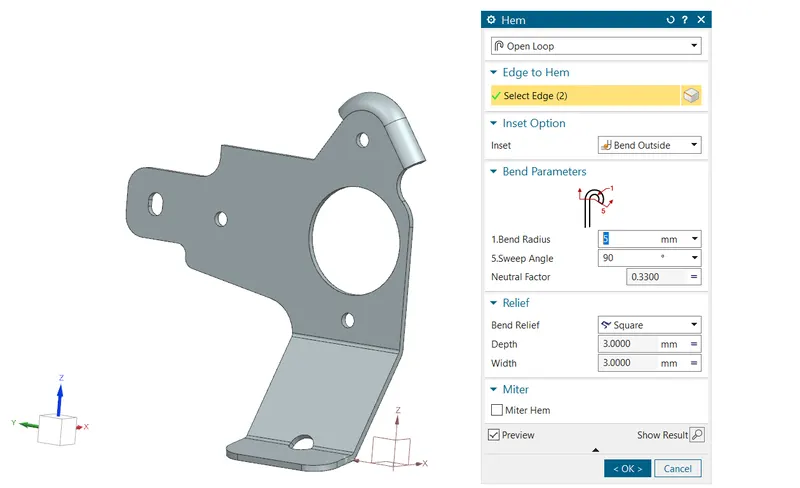
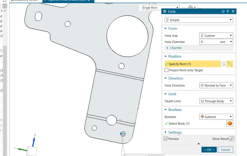
7.Hole -hole command is used to provide mounting holes for the bracket.
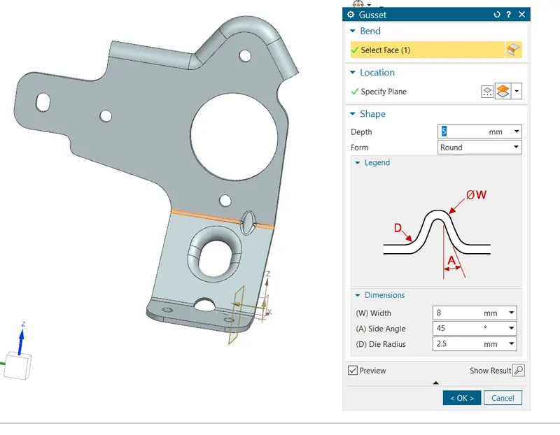
8. gusset -The gusset is a stiffening feature created as bends to curb the spring back effect and prevents the sheet metal from deviating from the formed shaped.Gusset is formed by choosing the bend at which it needs to be created. Then a face is selected parallel to which gusset is required. Perpendicular distance from the face where gusset should be located can be additionally specified.
9. Flat pattern -Create a flattened (unbent) sheet metal view in the drafting.
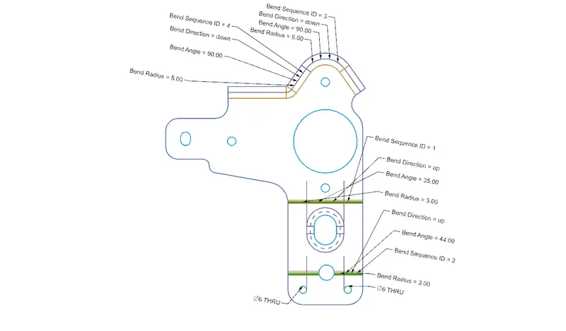
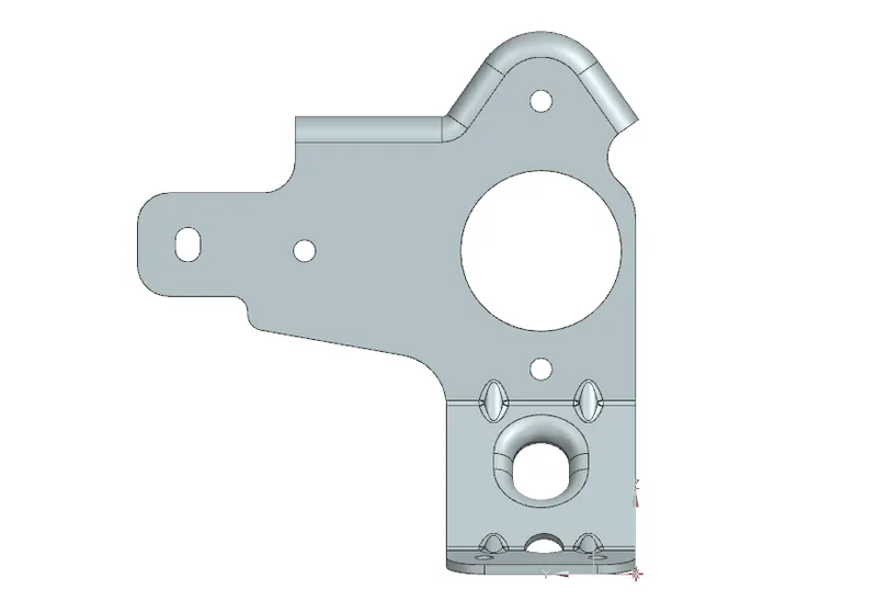
Different views of metal bracket
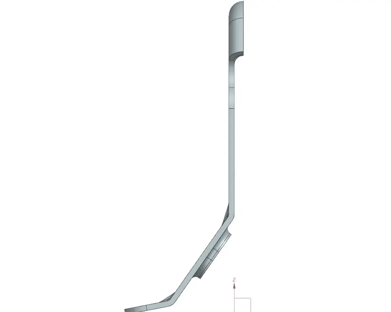
Front view
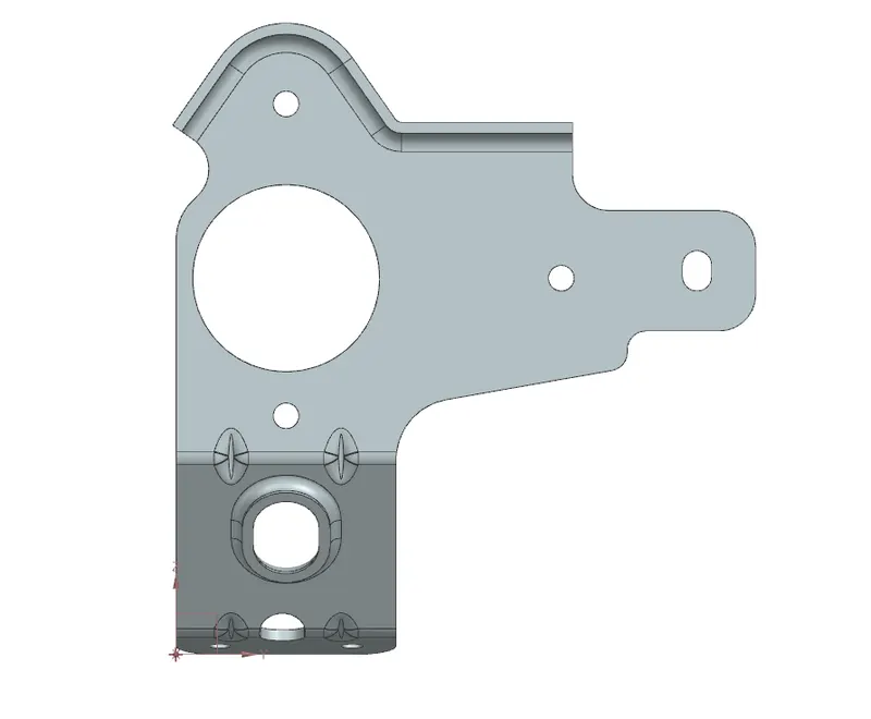
Right view
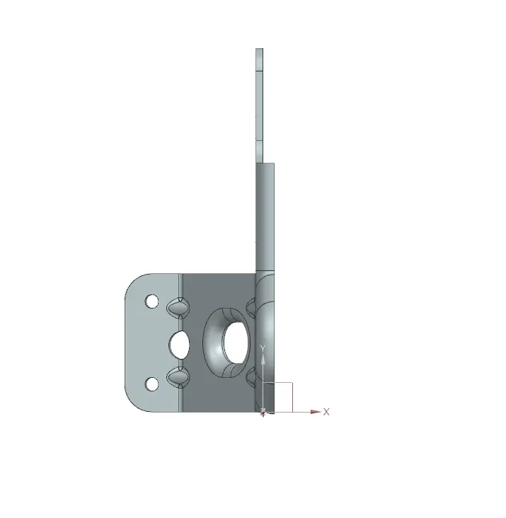
Top view
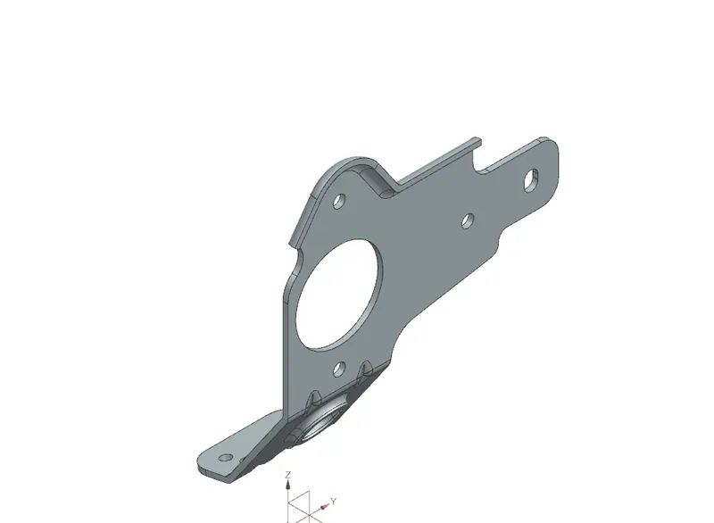
Isometric view
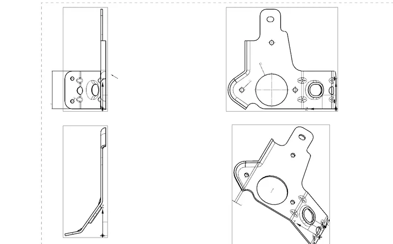
Drawing sheet
Conclusion
I have Successfully Completed the challenge of sheet metal bracket desig-2 by using NX CAD.