Advanced Sheet Metal Design Using NX Cad Challenge_7_ Metal bracket-II
Bracket 2 Design
Objective-
To design a Bracket Design using NX Siemens sheet metal workbench.
Introduction-
To design a Bracket using Nx Siemens sheet metal workbench which can be used for in an assembly for component support. The bracket is designed with press technology that provides strength even if sheet metal of 3mm thickness.
Design methodology-
The tutorial pdf is analysed thoroughly. The topology of the model is checked and all the features and specifics are noted.
- Sketch ( Base)
- Contour Flange ( solid sheet extrusion)
- Normal Cutout
- Break Corner
- Unbend
- Hole
- Advance Flange
- Rebend
- Gusset
Description-
- Sketch (Base) – The casing base sketch is produced using the sketch tools like rectangle. All dimensions are provided to get a fully defined sketch. The sketch parameter are so defined that future modification in sketch can update the complete model.
- Contour Flange – We can use the Contour Flange command to create a flange by extruding a sketch along a vector, or by sweeping a sketch along an edge or chain of edges. NX adds bends automatically using the default bend radius value. We can use different bend radius value, draw arcs in the section, or change the default bend radius value. We can use the contour flange as the base feature of a new sheet metal part, or add the contour flange as a secondary feature.
- Cutout – We can use the Cutout command to create openings in sheet metal tabs. The cutout feature only require a position and a sketch. Unlike extrude cut this feature still keeps the sheet metal parameters that can be accessed during the Bend and Rebend commands.
- Bend – We can use the Bend command to modify the model by bending material on one side of a sketch line or adding a bend between the two sides. We can create a bend on a planar face of a sheet metal body these particular bends can be flatten for manufacturing and can be rebend again as it also retain its bend parameters. If the part has multiple sheet metal bodies, we can specify the target face on which you want to create the bend. We can create a bend across existing Bead, Dimple, or Drawn Cut-out features. When we create such bends, the bend line must pass completely through the deform features.
- Unbend - Use the Unbend command to unbend a portion of the part to construct cutout features, hole features, or deform features across a bend. You can later reform the bend to represent the true formed state of the model. We can flatten non-uniform thickness bends that are created when we apply blends or chamfers, tapered holes in the bend region. After the unbend operation, NX retains the features that we apply or create in the bend region.
- Beads - We use the Bead command to lift material along the contour of a sketch that simulates a stamping tool. The main purpose of Beads is to stiffen sheet metal parts. We can create beads on bends in the folded or flattened state. A bead created on a bend in the folded state cannot traverse the bend. We can also create beads on deform features in sheet metal parts.
- Hole- We use the Hole command to create holes on solid or sheet by using points or circles as references.
- Advance Flange - We use this command to add a flange along an edge using a bend angle or a reference face. The edge and reference face can be curved. We can select a single edge or a chain of tangent edges. This command is useful when we want to create non-linear flanges, or when we work with sheet metal support structures in complex assemblies. The advanced flanges that we create on linear edges of a body work like regular flanges. To create more accurate flat representations, we need to apply compensation for material deformation at the start and end of the advanced flange edge chain.
- Gusset - We use the Gusset command to create a stiffening feature on a part. We can create strengthening features where extra strength is required in the bend region. We can create punched or embossed shapes in bend regions of sheet metal parts. We can create punched or embossed shapes in bend regions of sheet metal parts.
Views-
Front View
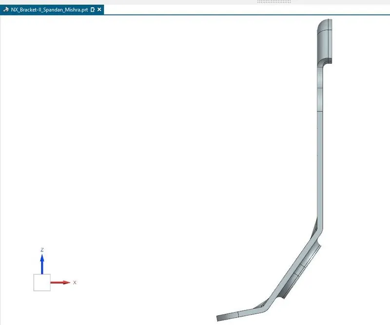
Top View
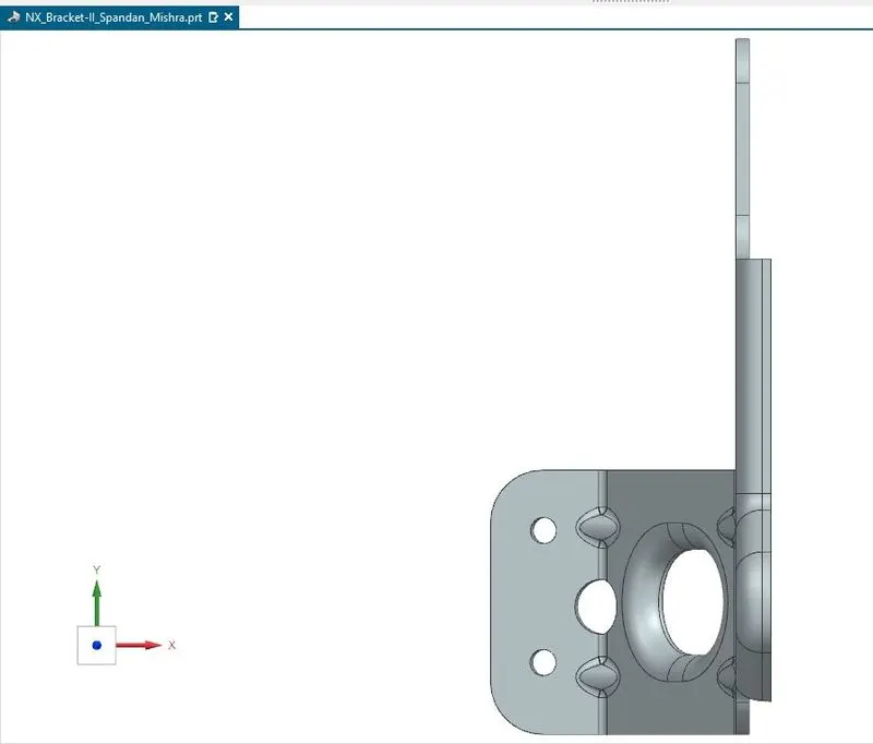
Right View
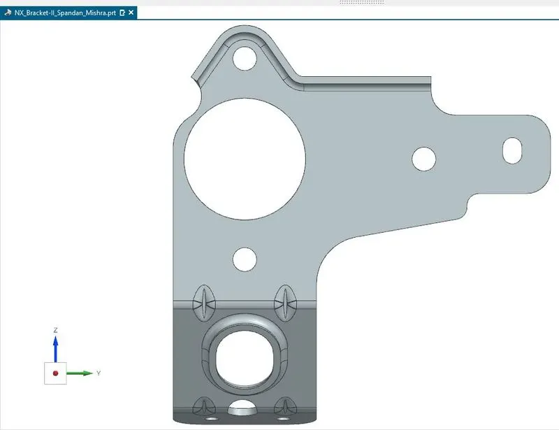
Isometric View
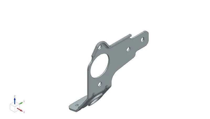
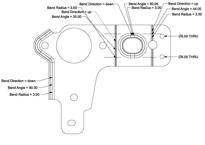
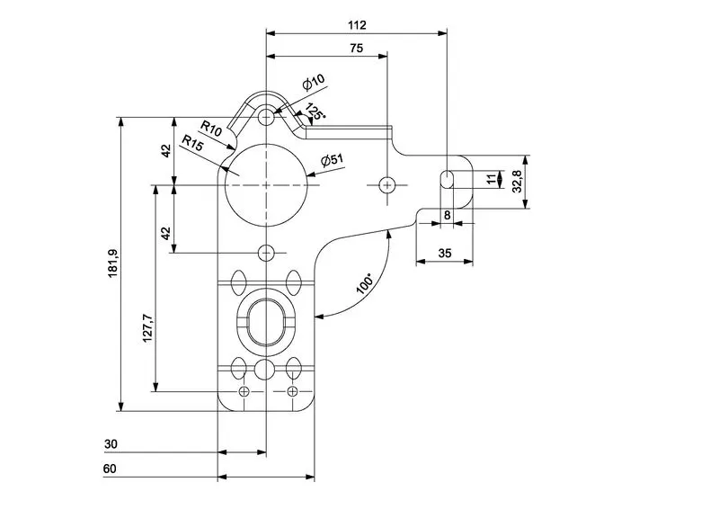
Drafting
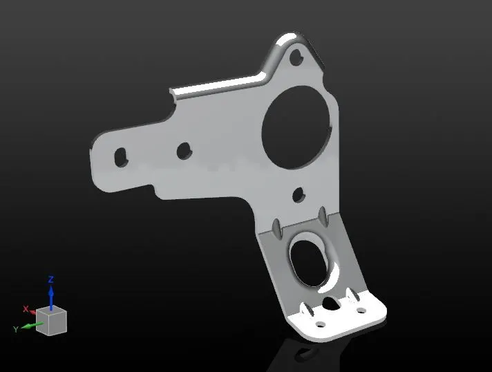
Render
Conclusion-
Thus the Bracket is designed and constructed.