Advanced Sheet Metal Design Using NX Cad Challenge_7_ Metal bracket-II
Objective:
The objective of this project is to create a sheet metal bracket using Siemens NX sheet metal.
Introduction:
Sheet metal is metal formed by an industrial process into thin, flat pieces. Sheet metal is one of the fundamental forms used in metalworking, and it can be cut and bent into a variety of shapes. Countless everyday objects are fabricated from sheet metal. Thicknesses can vary significantly; extremely thin sheets are considered foil or leaf, and pieces thicker than 6 mm (0.25 in) are considered plate steel or structural steel.
Design Methodology:
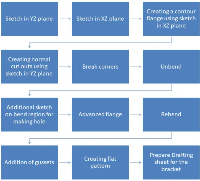
Description of tools/features:
Sketch : This the basic or common feature use in any type of modeling but it plays an vital role as it is the foundation of our part model.
Tab : This feature is used to create a solid body by extruding the sketch along a vector by given thickness value or it is also use to add material along a planar face.
Flange: Flange consists of one bend region and one web region with respective of any edges with required length and angle.
Bend: It gives a smooth radius to the sharp edges with the required radius.
Unbend: It is use to create a flat sheet of our sheetmetal model, it does by unbending the bend and material adjacent to the bend.
Extrude: Used to create a 3D solid from an object that encloses an area or a 3D surface from an object with open ends.
Hole: For creating a screw type, a screw size hole feature is used.
Bead : It lifts material along a contour of the sketch thereby acting like a stamping tool.
Flat Pattern: This will automatically create a flat surface of the model which helps for manufacturing.
Views of model:
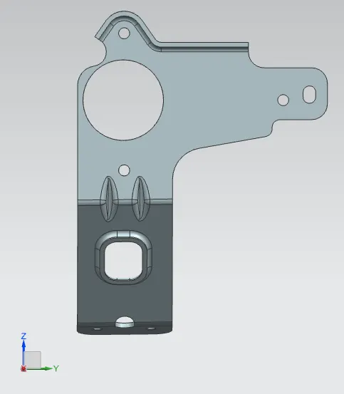
Front View:
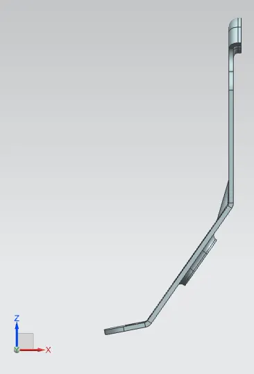
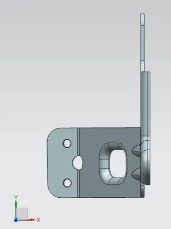
Side View:
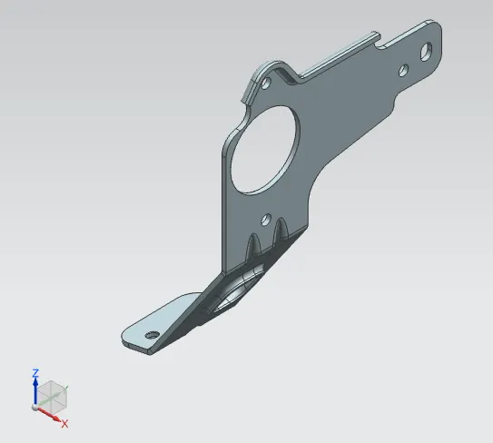
Isometric View:
Top View:
Conclusion:
The sheet metal bracket was successfully designed using Siemens NX CAD Sheet metal.