Advanced Sheet Metal Design Using NX Cad Challenge_7_ Metal bracket-II
1.Title of the project: Advanced sheet metal design using NX cad Challenge_7_Metal bracket-II
2.Objective: To design a Bracket using 2D Drawing using Siemens NX Sheet Metal Application.
3.Introduction:
- Sheet metal: It is formed by an industrial process into thin, flat pieces, it is one of the fundamental forms used in metalworking and it can be cut and bent into a variety of shapes.
- NX: It is formerly known as “Unigraphics” and is an advanced high-end CAD/CAM/CAE, which has been owned by Siemens PLM Software. Mostly it is used for Design, Engineering analysis, manufacturing.
4.Methodology:
Design methodology can be explained by the following flow chart.
|
Start |
|
A 2D Sketch of Desired Dimension was created in XZ plane (Front Plane) |
|
The flange was created in Y-Axis of thickness 3mm and width of 200 mm using the feature COUNTER FLANGE |
|
A 2D sketch was drawn with the desired dimension for removing the unwanted portion. |
|
An unwanted portion was removed using the feature NORMAL CUT |
|
Corners were trimmed using the feature BREAK CORNER with the desired dimension |
|
In the top plane, a sketch was created for Bead |
|
The sheet metal was unbent for creating a-holes and then was rebent. |
|
A new plane was created at a distance 203 mm from the datum plane for generating a closed top by using the feature Tab of thickness 2mm. |
|
End |
|
The edges of the upper edge were modified by using the feature Hem |
5.Description:
Step1: A 2D Sketch of Desired Dimension was created in XZ plane (Front Plane)
Step2: Flange was created in Y-Axis of thickness 3mm and width of 200 mm using the feature COUNTER FLANGE
Step3: A 2D sketch was drawn with the desired dimension for removing the unwanted portion.
Step4: Unwanted portion was removed using the feature NORMAL CUT
Step5: Corners were trimmed using the feature BREAK CORNER with the desired dimension
Step6: In the top plane, a sketch was created for Bead
Step7: The sheet metal was unbent for creating a-holes and then was rebent.
- Different Views of the model:
Top view:
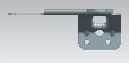
Side view:
Front view:
Isometric:
7.Detailed Drawing Sheet
8.Conclusion:
in this challenge, I have learned how to produce brackets using 2D Dwaings.
9.Drive Link:
https://drive.google.com/file/d/14MihdId0_zJlYdDB1tfwJb7fonfcGDFW/view?usp=sharing