Advanced Sheet Metal Design Using NX Cad Challenge_7_ Metal bracket-II
MODDELING AND DRAFTING OF METAL BRACKET USING NX SHEET METAL APPLICATION
OBJECTIVE:
- Analysis of given sketch and create a sheet metal part/bracket according to it.
- To learn different commands of NX Sheet Metal and using it to create our model.
INTRODUCTION
Sheet metal is metal formed by an industrial process into thin, flat pieces. Sheet metal is one of the fundamental forms used in metalworking, and it can be cut and bent into a variety of shapes.
Creating fast, accurate flat patterns is the goal of any organization that manufactures products which contain sheet metal parts. NX Sheet Metal provides a set of tools within the NX design environment that allows for simple and fast design of sheet metal parts, dependent on their material and manufacturing process. In this project we will learn to use them and create a sheet metal bracket using NX Sheet Metal and its commands.
DESIGN METHEDOLOGY:
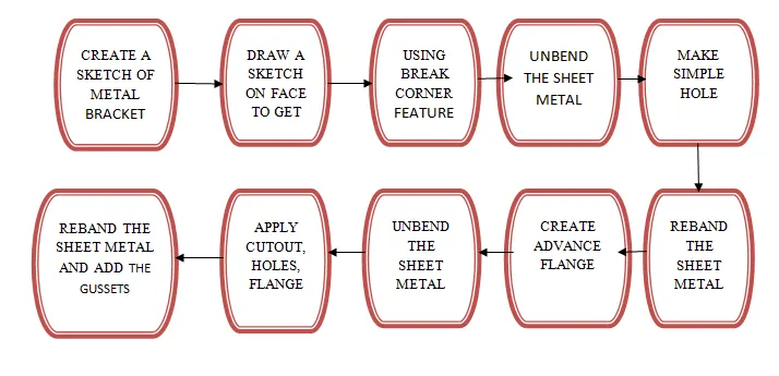
Description (Tools/Features):
- SKETCH :- 2D sketch using which 3D features are created.
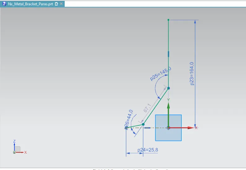
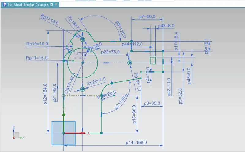
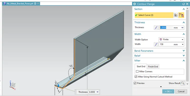
- CONTOUR FLANGE :- It is used to create a flange along a contour at a particular angle.
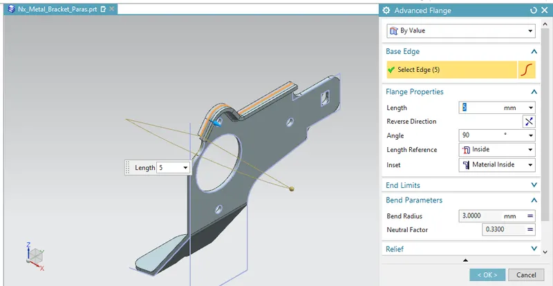
- ADVANCED FLANGE :- Add a flange along an edge at a given bend angle or a reference face.
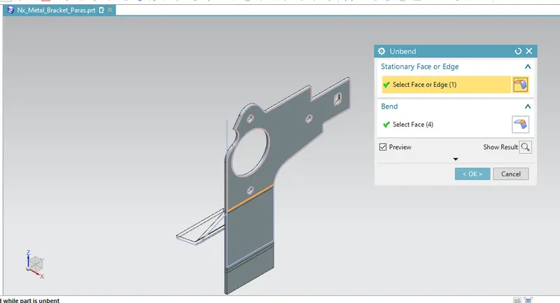
- UNBEND :- This feature is used to unbent the sheet metal taking any one face as a stationary face.
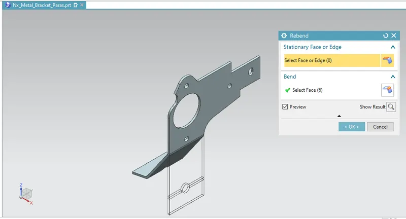
- REBEND :- It is used to rebend the sheet metal.
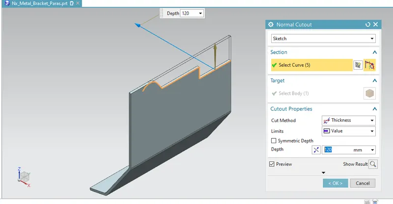
- NORMAL CUTOUT :- Removes/cuts a portion of the sheet metal using a sketch.
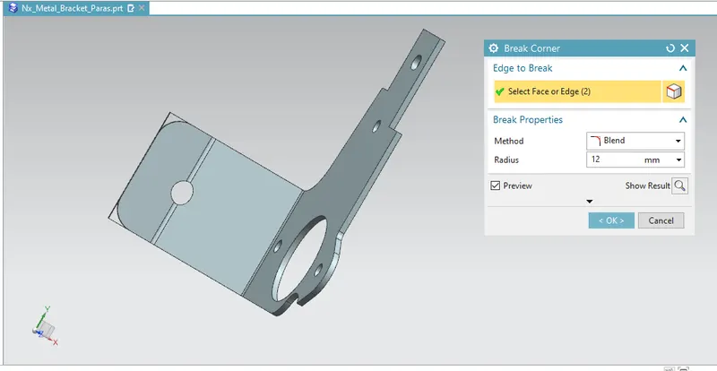
- BREAK CORNER :- Smoothen the corners by applying a fillet or a chamfer.
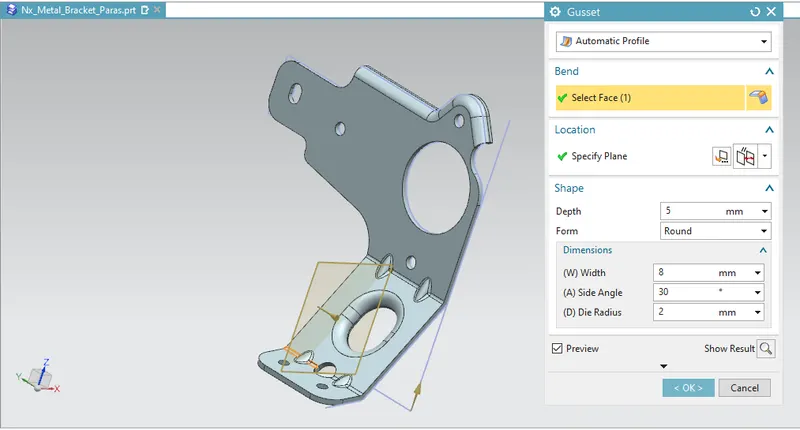
- GUSSET :- Add perpendicular support structures to stiffen up the sheet metal component.
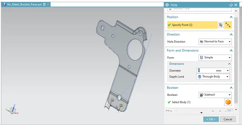
- SIMPLE HOLE:- Create round cut-outs or just plain simple holes.
DIFFERENT VIEWS OF THE MODELS:
FRONT VIEW:
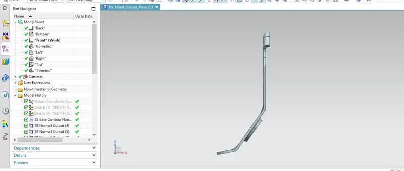
TOP VIEW:
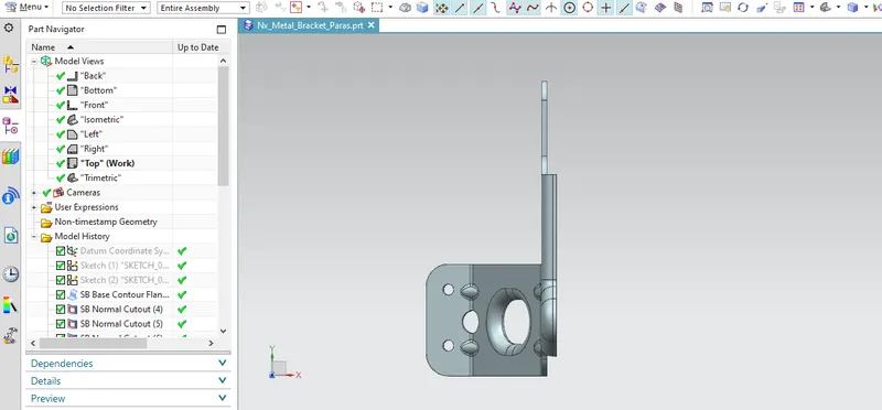
SIDE VIEW:
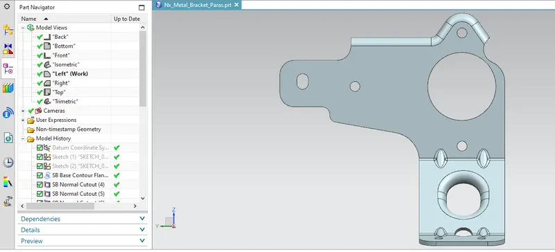
ISOMETRIC VIEW:
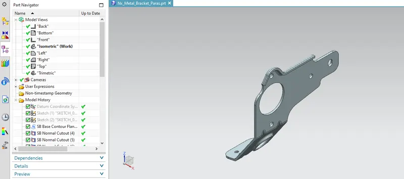
TRIMETRIC VIEW:
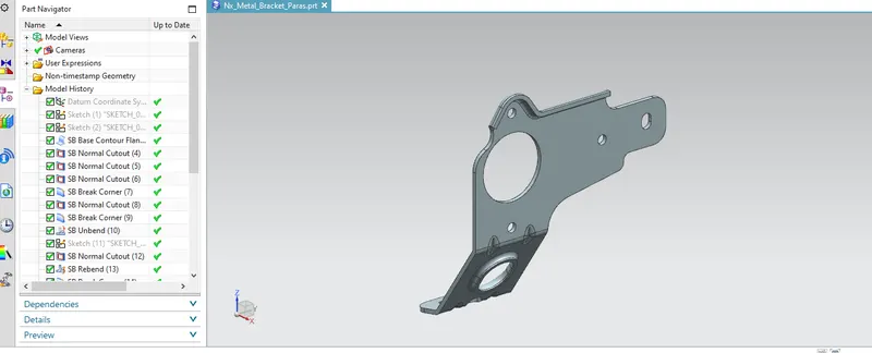
Conclusion: Successfully modeled a sheet metal bracket using NX Sheet Metal application.