Advanced Sheet Metal Design Using NX Cad-Bracket
Designing of a Bracket
Objective: To design a ‘Bracket’ using Siemens NX Sheetmetal Application.
Introduction: For studying different tools and features used for designing sheet metal design parts, this project was selected. This project was mainly focused in providing an idea about the workflow in creating a part design and to familiarize certain tools in this application.
Design Methodology:
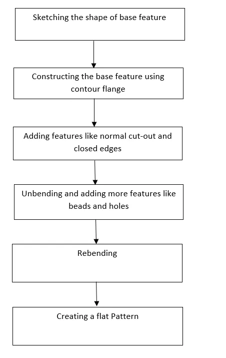
As shown in the flowchart, I started by sketching the base feature and it was constructed by using the contour flange. Then certain additional features like normal cut-out and closed edges were added to the base feature. Then after that it is unbended and feature like beads and holes were applied on the base feature. Then it was rebended and a flat pattern was applied.
Description:
For designing of a Bracket the following features were used:
- Contour Flange: To create a main base flange by extruding a sketch with required properties.
- Break corner: To round the sharp edges of tabs and flanges.
- Bead: To lift material along the contour of the sketch.
- Unbend: To flatten the bend features.
- Hole: To provide general hole with features to specified points.
- Normal Cut-out: To create a cut based on the sketch input.
- Rebend: The unbended features are bended using this feature.
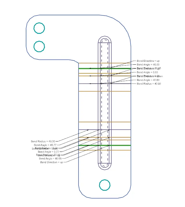
- Flat Pattern: Used to create a flat pattern for draft purposes.
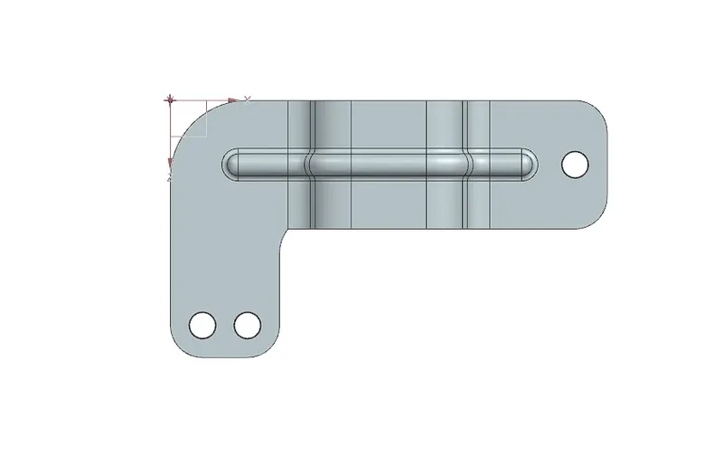
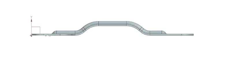
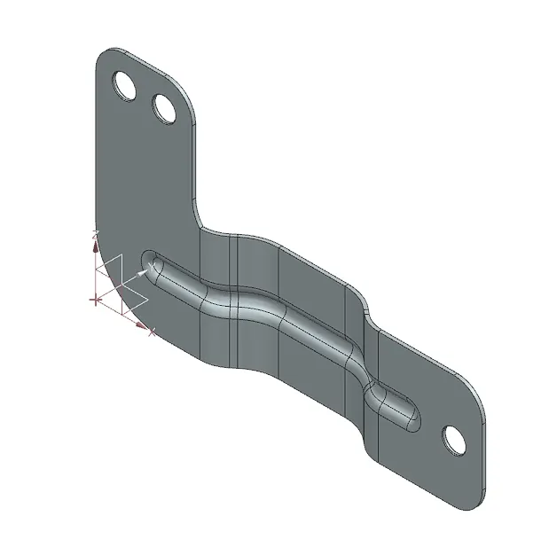
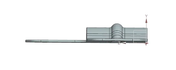
Bracket
1.Top view
2.Front View
3.Isometric View
4.Side View
5.Flat Pattern
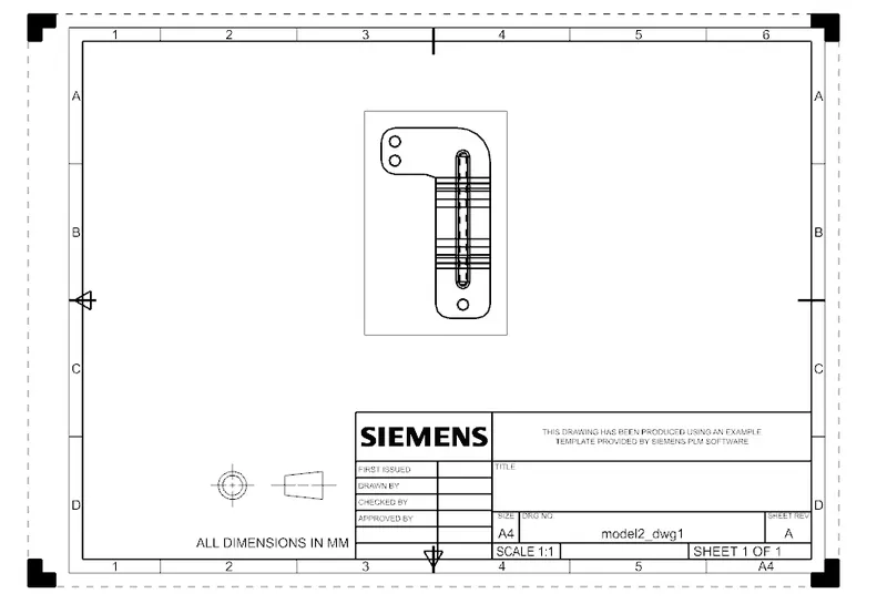
6.Draft Image
Conclusion: A 'Bracket' was designed using Siemens NX Sheetmetal Application.