Advanced Sheet Metal Design Using NX Cad Challenge_6_Bracket
Bracket using 2d drawings
OBJECTIVE: To make sheet metal design of bracket using 2D drawing in NX.
SHEET METAL: Sheet metal is metal formed by an industrial process into thin, flat pieces. Sheet metal is one of the fundamental forms used in metalworking, and it can be cut and bent into a variety of shapes. Countless everyday objects are fabricated from sheet metal.
SHEET METAL DESIGN IN CAD: Sheet metal design software considers the fabrication methods needed for manufacturing. The flat pattern can be used to document and manufacture associatively as the design changes.
DESIGN METHODOLOGY:
| 1. | sketch the profile |
| 2. | do counter flange. |
| 3. | again sketch for the cutout |
| 4. | do normal cutout |
| 5. | sketch profile for bead |
| 6. | unbend the part |
| 7. | apply bead |
| 8. | apply holes |
| 9. | do local radius analysis |
| 10. | measure distance between holes |
| 11. | rebend the part |
| 12. | bracket is completed. |
Features used for making casing:
- Sketch
- Counter flange
- Normal cutout
- Break corner
- Unbend
- Bead
- Rebend
- Local radius
- Hole
- Measure distance
Let us discuss the above features in detail:
- Sketch: this feature is present in modelling application. It create sketch, add curves, dimensions, constraints. Used for creating sketch for tab, normal cutout, unbend.
- Normal cutout: this feature removes material by projecting a sketch onto the model and then cutting perpendicular to faces intersected by the projection.
- Break corner: It rounds or chamfer the sharp edge of a tab or flange.
- Contour flange: it adds base feature by extruding a sketch along a vector or adds material by sweeping a sketch along edge or chain of edges.
- Local radius: Calculates geometric properties of selected points on curve, edges and faces.
- Measure distance: calculates the distance between two objects; be it two points ,line,arc,etc.
- Unbend: Flattens the bend and the material adjacent to it.
- Hole: this feature adds a hole to one or more solid bodies in a part or assembly.
- Beads: lifts material along the contour of sketch that simulates the stamping tool.
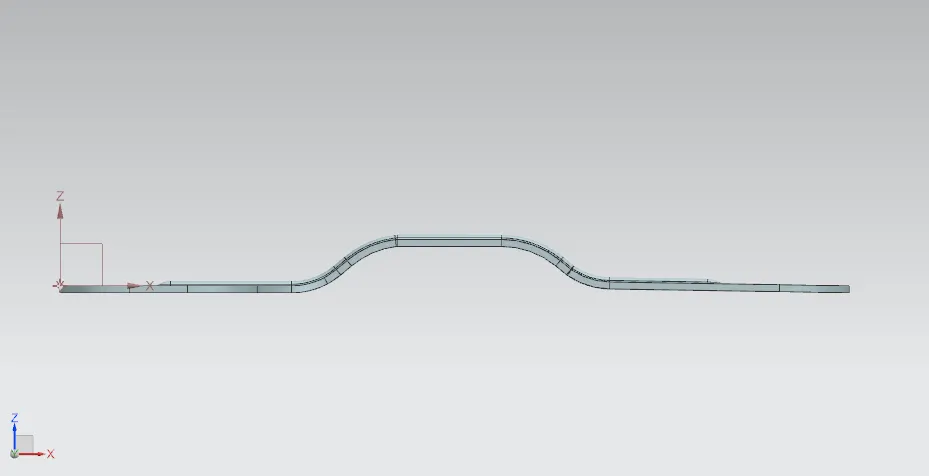
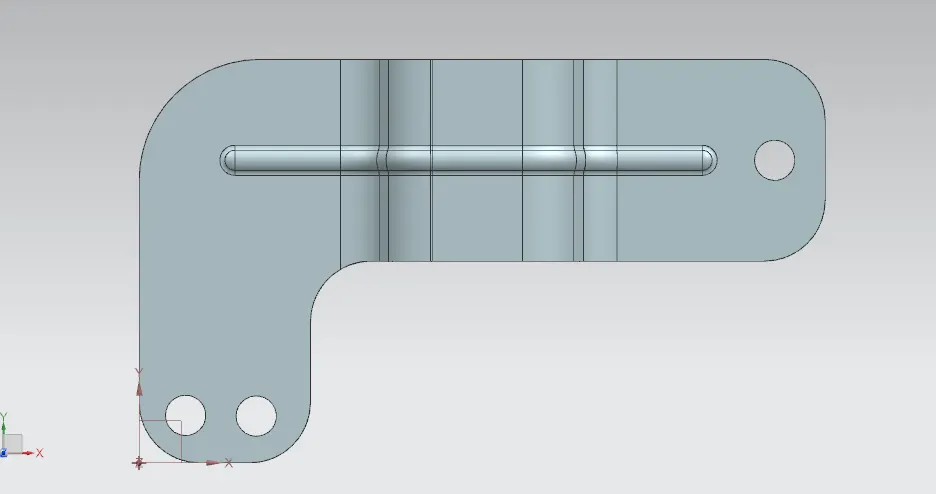
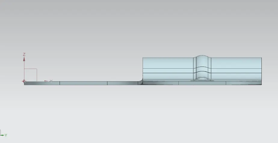
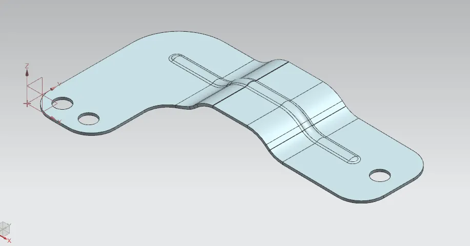
images of bracket:
front view
top view
side view
isometric view
Conclusion:
The design is formed in the nx 12 software and part is modelled in sheet metal application.
Learnt some features of the sheet metal workbench while making the design.
link
https://drive.google.com/file/d/1HkQEp8qpVFTIKEJX1S7niiZDVo0Y7Qac/view?usp=sharing