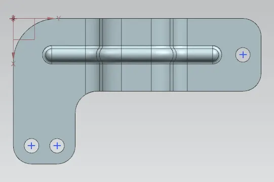
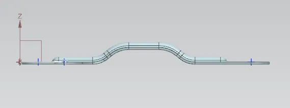
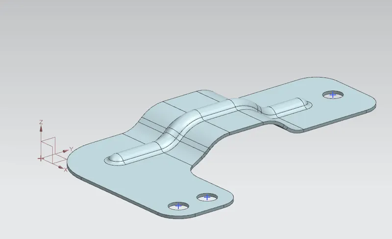
Advanced Sheet Metal Design Using NX Cad Challenge_6_Bracket
- Title of the Project:Advanced Sheet Metal Design Using NX Cad Challenge_6_Bracket
- Objective: To create the Bracket Model by using NX Software.
- Introduction :
Sheet metal:
Sheet Metal is a type of material that is flattened into thin sheets. Sheet metal is made by taking a large cast in and rolling it into a long ribbon of the thickness it wants. This flat metal is rolled into a coil and sent directly or cut the metal into sheets before being sent to a machine shop.
The sheets are made from different kinds of metals such as aluminum, brass, copper, steel, tin, nickel and titanium. The sheet’s thickness depends on the material needed for a project. Thicknesses can vary from 0.15 -6.00 mm significantly; extremely thin sheets are considered foil or leaf, and pieces thicker than 6 mm (0.25 in) are considered plate steel or “structural steel.”
Designing the products with the sheet metal comes with its limitations but has many benefits that can work with this design material that outweighs cons. It is available with numerous coating for corrosion resistance or surface finish.
Sheet Metal can be useful for large and durable parts with few features. They make good RF shields, ground planes and thicker gauge parts for adding strength and weight to the things. Sheet metal is not suitable for minimal parts, complex or precise geometry, cosmetic parts or lightweight parts.
Most of the metal fabrication businesses rely on 2D drawings even though the 3D model is available in the market. At the manufacturing floor, drawings are utilized to develop production plans. The purchasing department uses it for technical packages while other departments like quality and marketing utilize drawings to develop different publications.
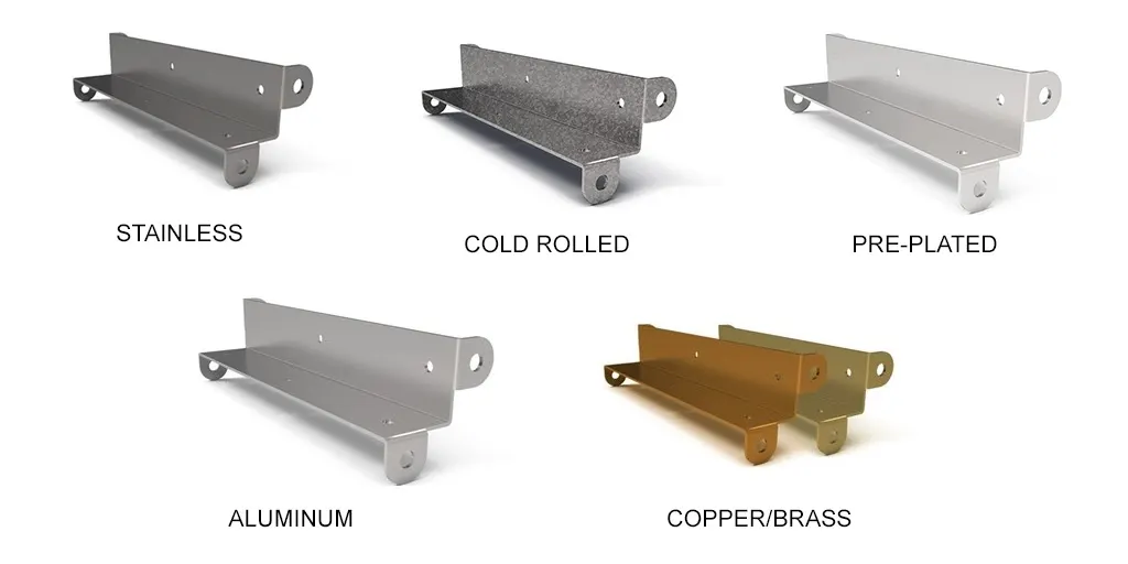
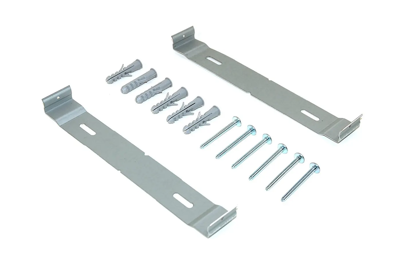
Bracket: In mechanical engineering a bracket is any intermediate component for fixing one part to another, usually larger, part. What makes a bracket a bracket is that it is intermediate between the two and fixes the one to the other.
4.Design methodology:
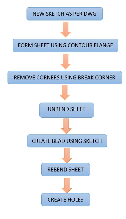
Description:
here explaining about the used features used in modelling of bracket.
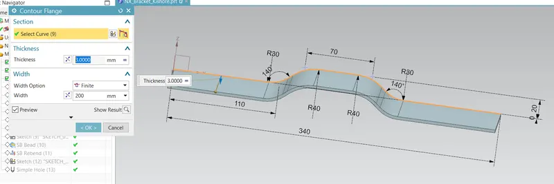
CONTOUR FALANG:
Contour flange command is used created the bended sketch to form the sheet
which is easily helped to form the bende sheet metal features.

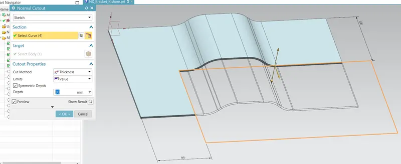
NORMAL CUTOUT:
Normal Cutout option is used to cut the sheet in required shape as per the sketch
it will helps to cut and the sheet
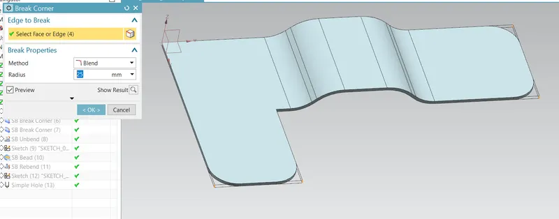
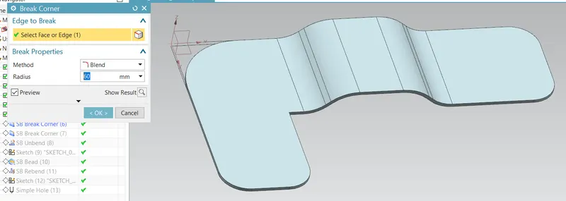
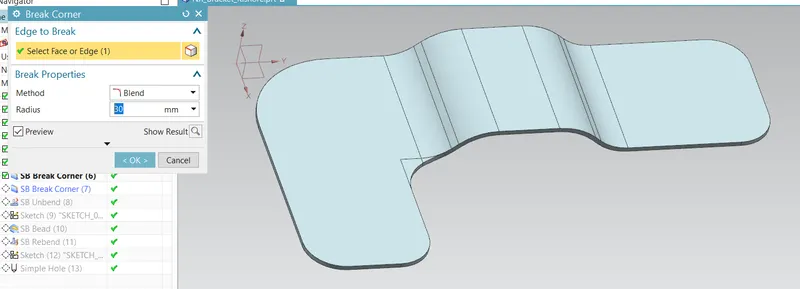
BREAK CORNER:
Break corner is used to delete the sharp corners of the sheet metal and form smooth corners
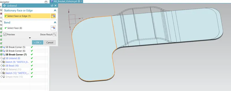
UNBEND:
this command is used to unbend the bended sheet and forms in flat surface
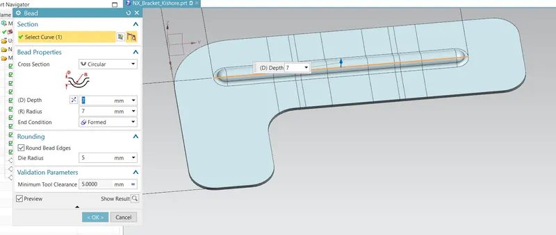
BEAD: this command will lifts the material along counter of sketch that stimulates the stamping tool, and increase the stregth locally
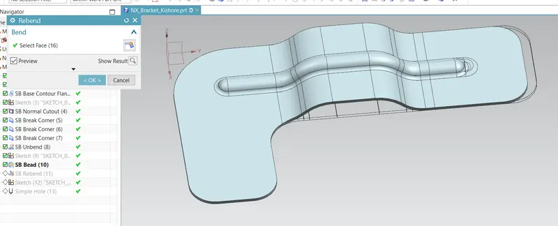
REBEND:
this command will help us to form unbebded sheet to former position as bended shape
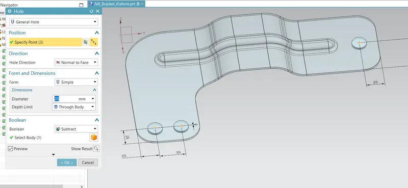
Holes :
This option will create the holes on the sheetas required
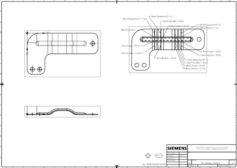
Drawing Created and Views and flat pattern added
Conclusion: Here we have understand how to create the Bracket by using NX Sheet metal
Views: