Advanced Sheet Metal Design Using NX Cad Challenge_6_Bracket
Bracket
Objective:
To design a Bracket using the Siemens NX Sheet metal application.
INTRODUCTION :
In this project, we will see a step-by-step procedure for creating a bracket in Siemens NX-12. All the features used during the creation are briefly explained. We will learn about them and see how to use them too.
DESIGN METHODOLOGY:
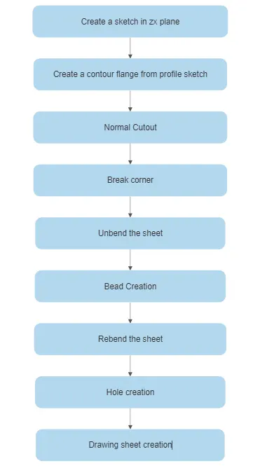
Description:-
Sketch; Design a sketch for the first step of the model.
Tab; After sketch will be using the tab option in the base feature.
Flange; Flange option to use the extended part of the sheet metal.
Contour Flage; It is used to extend the model of the long distance.
Sheet metal Cutout; It is sketched on opposite sides to cut out the overall shape of the sketch.
Unbend; It is used to sheet metal taking anyone's face as a straight stationary face.
Rebend; It is used to rebend the unbend face of the model.
Bead; It will be used to give strength to the sheet metal.
Local Radius Analysis; To measure the radius formed in sheet metal.
Screenshots:-
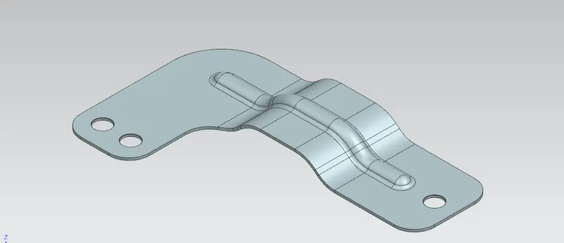
Isometric view
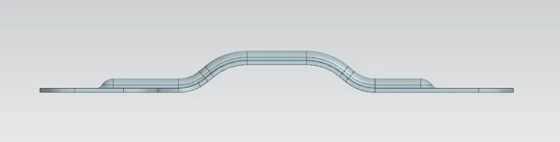
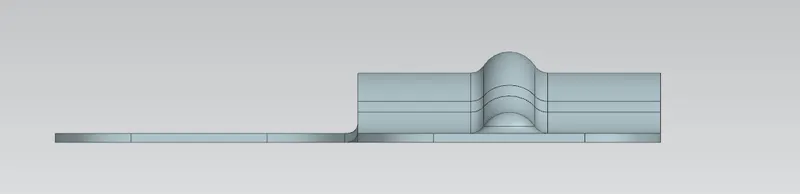
Front view
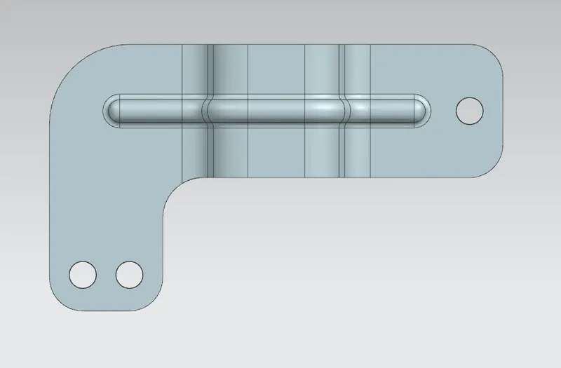
Top view
Side view
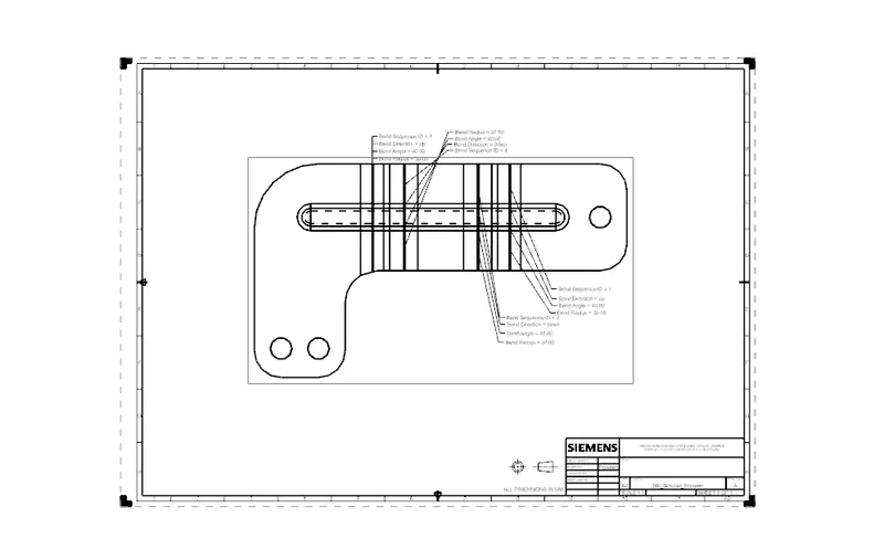
Drawing Sheet
Conclusion :
The bracket is created is using advanced sheet metal tools in NX CAD.