Advanced Sheet Metal Design Using NX Cad Challenge_6_Bracket
Features used in the design of the Bracket:
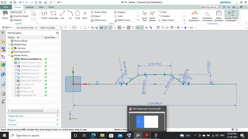
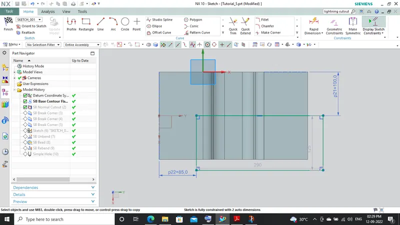
- Sketch This the basic or common feature use in any type of modeling but it plays a vital role as it is the foundation of our part model. NX-CAD provides several sketch entities and tools for creating sketches such as line, arc, rectangle, spline, circle, ellipse, polygon, etc. In the case of our bracket, I have used sketch entities like rectangle, line, arc.
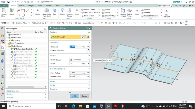
- Contour Flange: This is used to create a base feature by extruding the sketch along a vector or it adds material along the edge or chain of edges of the sketch by using this feature many complex shapes can be easily created by just creating the sketch of the edge and extruding it.
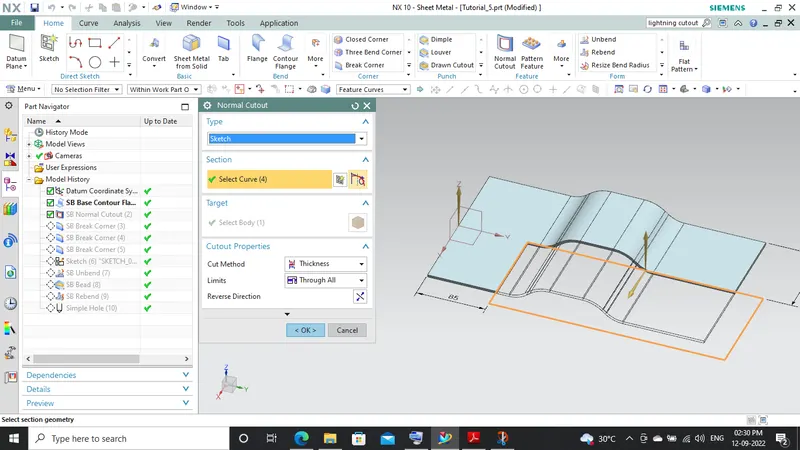
- Normal Cut-Out: This feature cuts or removes material from an existing solid body by projecting the sketch along with the model and then cuts perpendicular to the faces which intersect the projecting sketch.
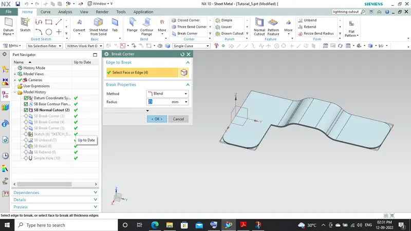
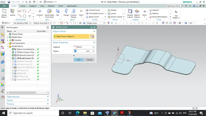
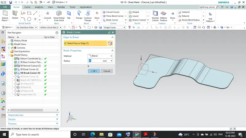
- Break Corner: It rounds or breaks the sharp corner of the tab created thereby providing a smooth round profile to the corners, it is been provided to give aesthetic look to our part but furthermore its main function is to provide safe and easy handling.
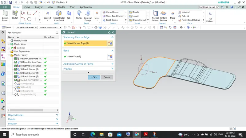
- Unbend: It is used to create a flat sheet of our sheet metal model, it does by unbending the bend and material adjacent to the bend.
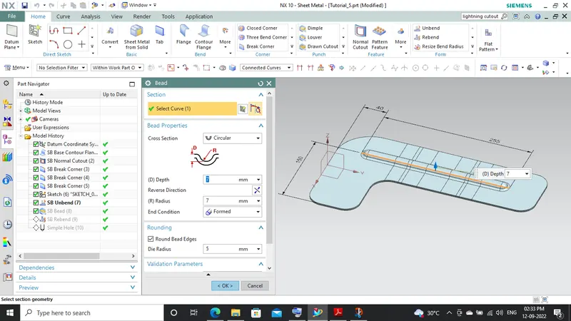
- Bead: It lifts material along a contour of the sketch thereby acting like a stamping tool.
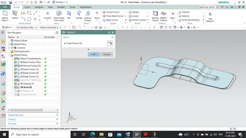
- Rebend: It again restores the bends given to the model previously and any other features added to the model after unbending.
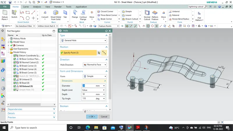
- Hole: It is used to create single or multiple holes by just providing the position of points at which the holes are to be generated of the required size. We can also create special holes such as counterbore or countersunk.
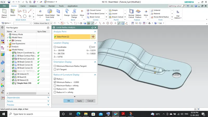
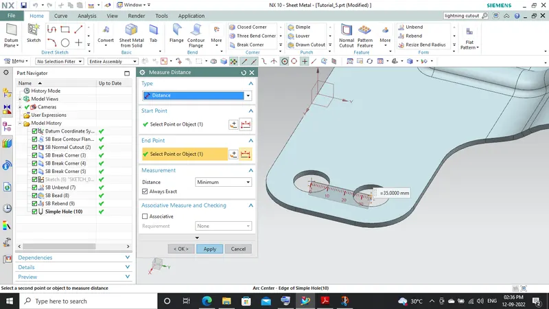
Anylysis Images:-