Advanced Sheet Metal Design Using NX Cad Challenge_6_Bracket
Design of Bracket by using NX CAD
Objective
To Design a L-shaped bracket by using NX CAD
Introduction
Sheet metal fabrication is the process of forming metal sheets to the desired shape using different manufacturing methods. The completion of a product usually comprises many steps from cutting and bending to surface treatment and assembling. Often times a variety of fabrication techniques can be used to achieve a similar end result. But the right choice is still existing, depending on the costs and needs.
There are many different industries that make use of sheet metal, whether it’s stainless steel, thin aluminum strips, or copper brass, here are a few industries that make frequent use of this material.
- Automotive
- Aerospace
- Construction
Design methodology
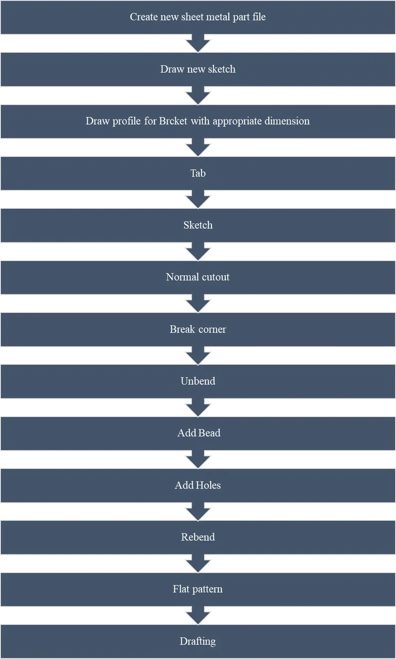
Features used
1. Contour flange -Creates main base flange or second flange by extruding sketch.
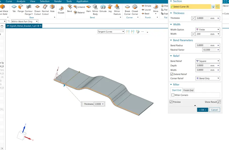
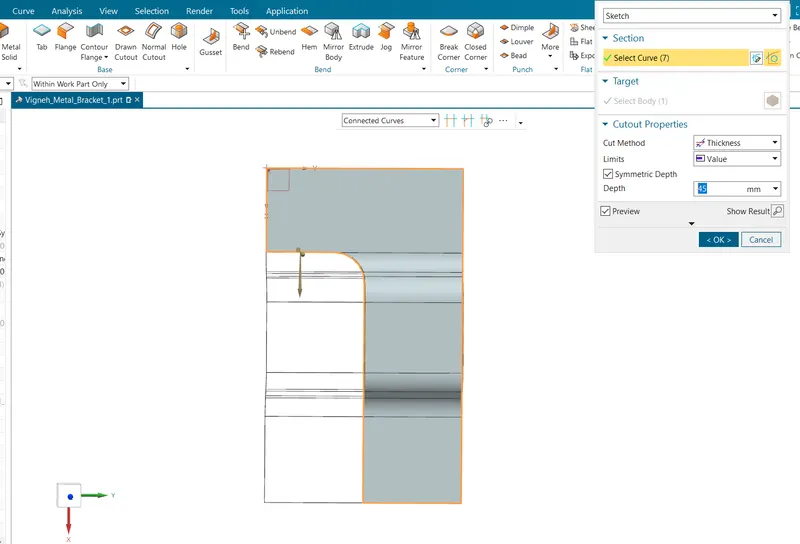
2.Normal cutout -Normal Cutout command extract volumes from sheet metal by using sheet metal production principles. Cutting faces will be perpendicular to the sheet metal surface.
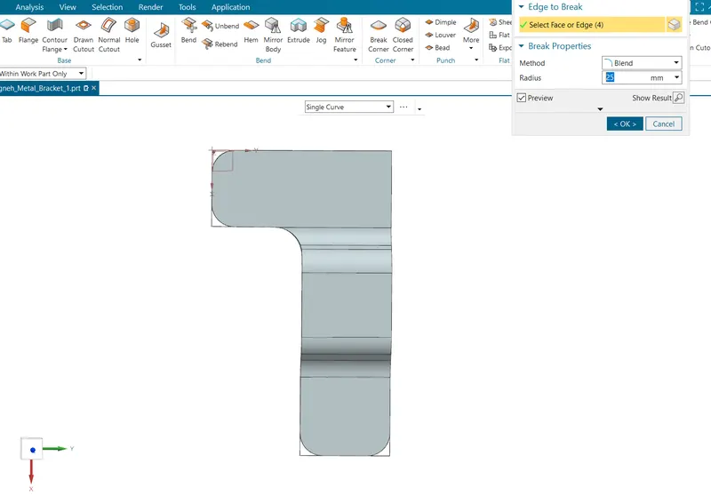
3.Break corner -Break corner is used to provide a fillet type faster to the sharp corners of the sheet metal. it is used to provide safety as well as to relieve stress concentration.
4.Unbend -Flattens sheet model through selected bends.
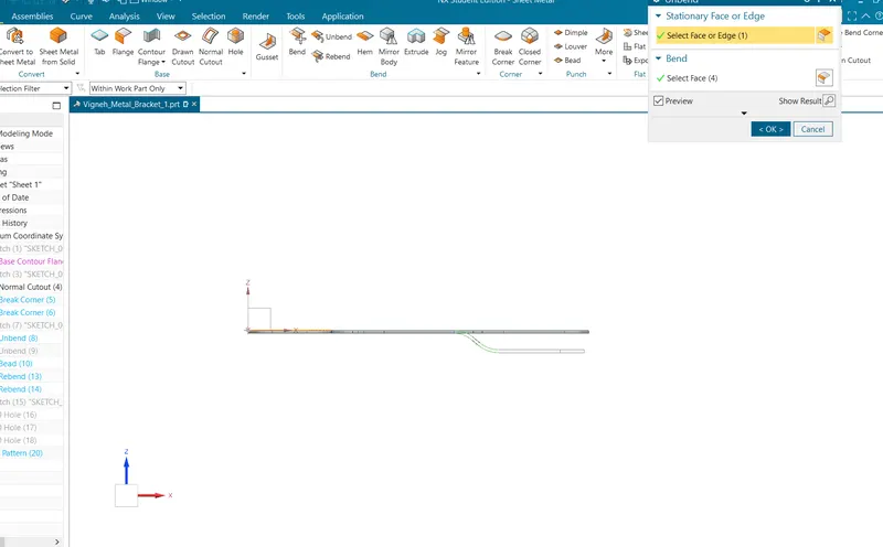
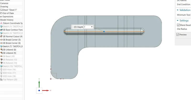
5. Bead -This feature is used to create a bead on the sheet which generally strengthens it.
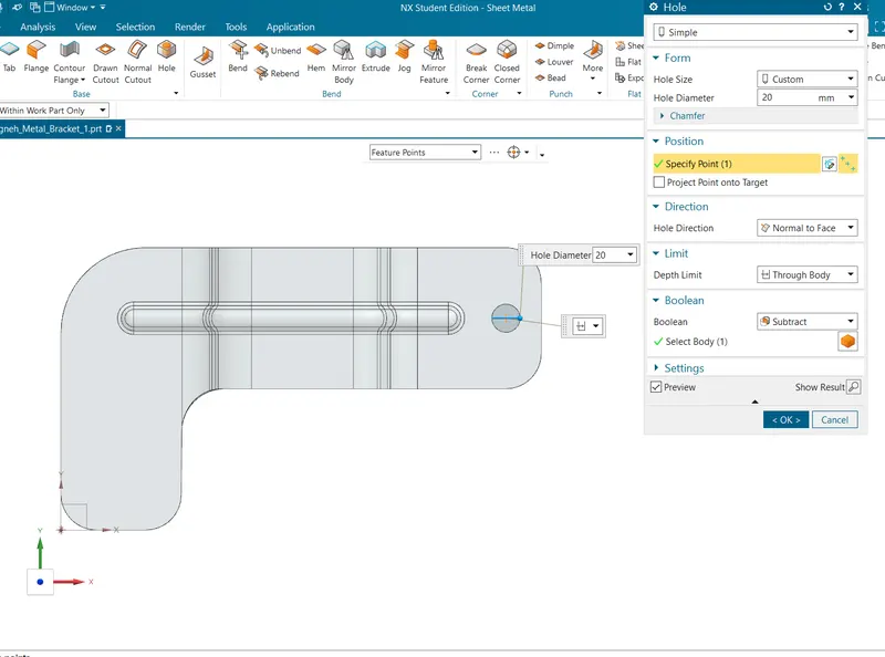
6. Hole -hole command is used to provide mounting holes for the bracket.
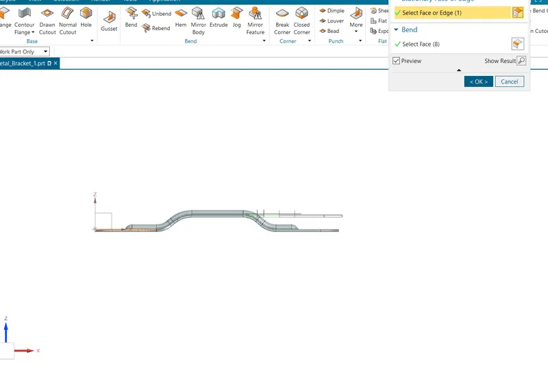
7. Rebend -Rebend is the unbent feature of the sheet metal model. It uses after the Unbend command If needed.
8. Flatpattern -Create a flattened (unbent) sheet metal view in the drafting.
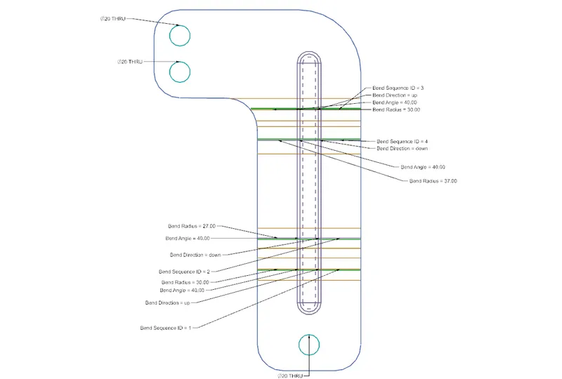
9. Drawing sheet
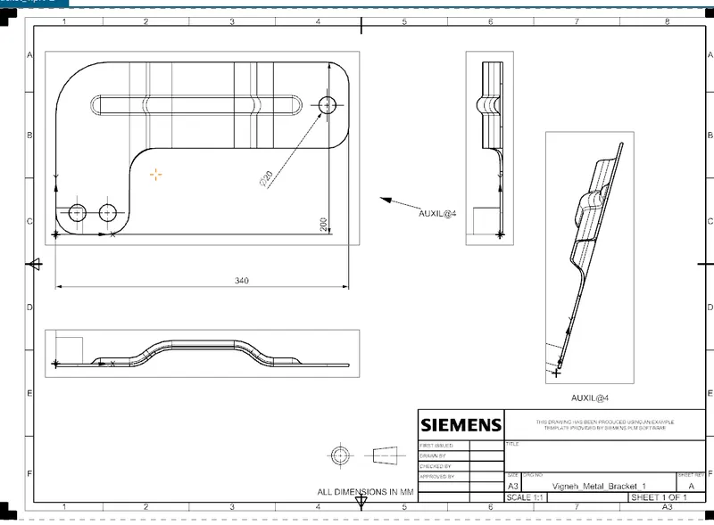
Different views of Bracket
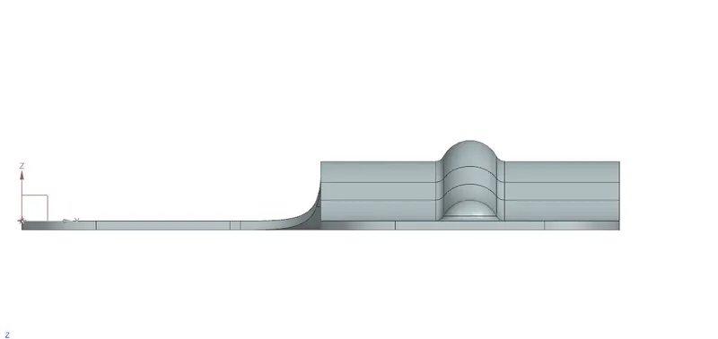
(Front view)
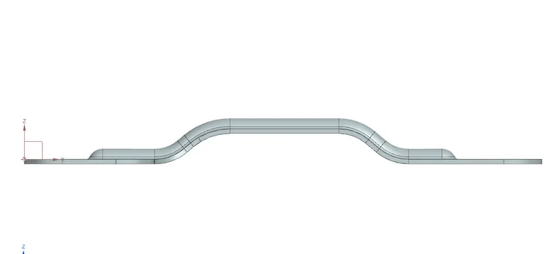
(Right view)
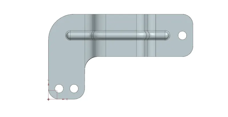
(Top view)
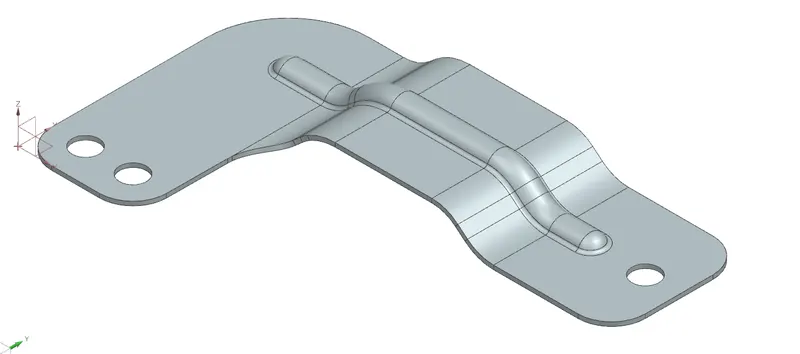
( Isometric view)
Conclusion
I have Successfully Completed the challenge of sheet metal bracket design by using NX CAD.