Advanced Sheet Metal Design Using NX Cad Challenge_6_Bracket
BRACKET DESIGN
Aim: To design a Sheetmetal Bracket using Siemens NX Sheetmetal Application
Introduction
Sheet metal is metal formed into thin, flat pieces, usually by an industrial process. Sheet metal is one of the fundamental forms used in metal working, and it can be cut and bent into a variety of shapes. The thicknesses can vary significantly; extremely thin sheets are considered foil or leaf, and pieces thicker than 6 mm are considered plate. Its thickness is quantified by a measure known as its gauge. The metal will be thin if the gauge number is larger. A wide range of products are manufactured with the use of sheet metal making it an essential part of the modern world. Sheet metal is used in automobile and truck bodies, major appliances, airplane fuselages and wings, tinplate for tin cans, roofing for buildings (architecture), and many other applications.
Design Methodology
Sketching => Making to 3D => Cutout required area => Breaking the corners => Unbending => Creating beads and holes => Rebending => Drawing Sheet creation
Modelling Steps
1. First of all, the required part sketch is created and is then created into a 3D model using contour flange command.
2. After that, the model is cutout in a required area using normal cutout command. And then the corners of the model is smoothed using break corner command.
3. After that, for creating various features like beads and holes, the model is unbended. And then the features are created using bead command and hole command.
4. After the creation of these features, the model is bended back using rebend command.
5. At last, after the completion of the model, that is for drafting the drawings of the model is created with the help of using flat pattern command. Then a new drawing sheet is created and using base view command and selecting the created flat pattern, the drawing of the model is created.
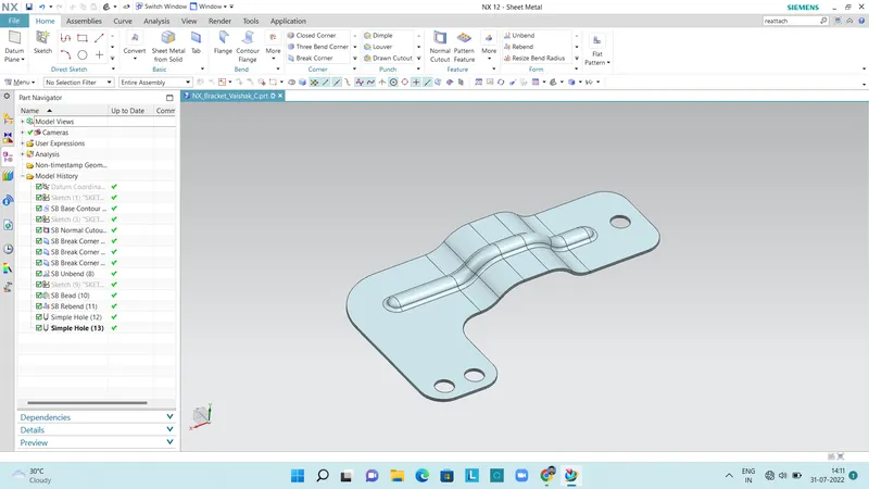
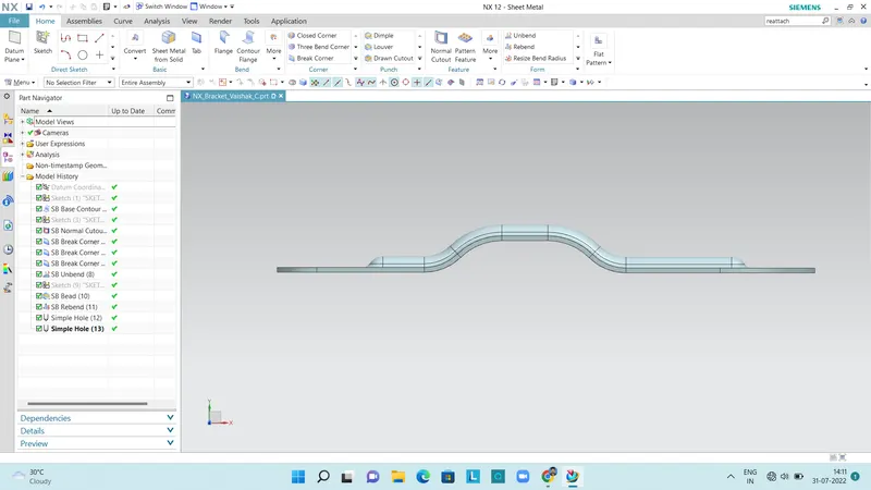
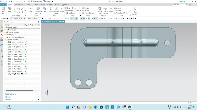
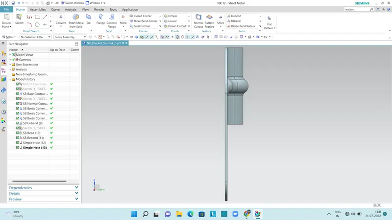
Final Model in Different views:
Detailed Drawing Sheet
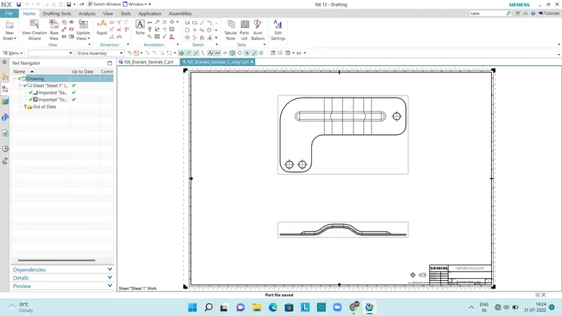
After the creation of model, the drawings of the model is created with the help of using flat pattern command. Then a new drawing sheet is created and using base view command and selecting the created flat pattern, the drawing of the model is created as shown above.