Advanced Sheet Metal Design Using NX Cad Challenge_6_Bracket
AIM:
To create a sheetmetal component of bracket using NX cad tool in sheetmetal workbench and create drawing for the component.
INTRODUCTION:
Sheet metal is metal formed by an industrial process into thin, flat pieces. Sheet metal is one of the fundamental forms used in metal working , and it can be cut and bent into a variety of shapes. Countless everyday objects are fabricated from sheet metal. Thicknesses can vary significantly; extremely thin sheets are considered foil or leaf, and pieces thicker than 6 mm (0.25 in) are considered "plate steel" or "structural steel".
Sheet metal is available in flat pieces or coiled strips. The coils are formed by running a continuous sheet of metal through a roll sitter
DESIGN METHODOLODY:
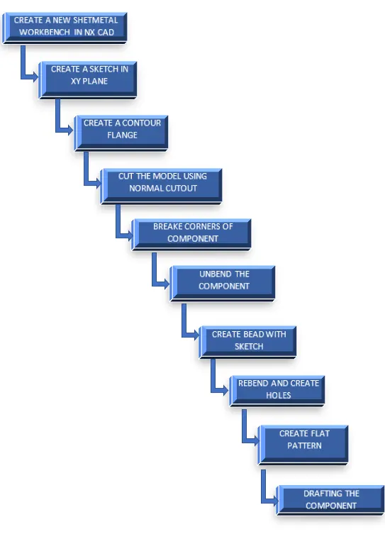
MODEL DESCRIPTION:
SKETCH:
2D Sketching in Drawings. You can create drawing geometry using 2D sketched geometry only, without reference to existing models or assemblies. ... When you drag a sketch point in a drawing, it snaps or infers to other sketches, drawing views, blocks, and items in the sheet format
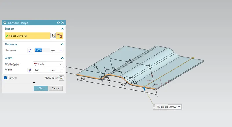
CONTOUR FLANGE:
Creates a base feature by extruding a sketch along a vector, or adds material by sweeping a sketch along an edge or chain of edges.
SKETCH:
2D Sketching in Drawings. You can create drawing geometry using 2D sketched geometry only, without reference to existing models or assemblies. When you drag a sketch point in a drawing, it snaps or infers to other sketches, drawing views, blocks, and items in the sheet format.
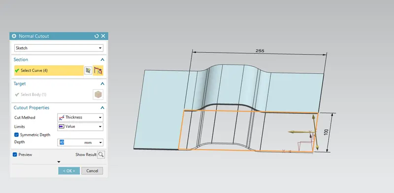
NORMAL CUTOUT:
The command is used to cut the material on the exists sketch on the plane.
BREAK CORNER:
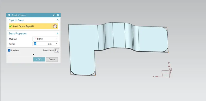
The break corner feature breaks the sharp edge in the corner and makes it round.
Break corner helps to prevent stress relief and fracture breaking and make the smooth corner.
It is used to avoid the crushing force of accidents due to sharp corners.
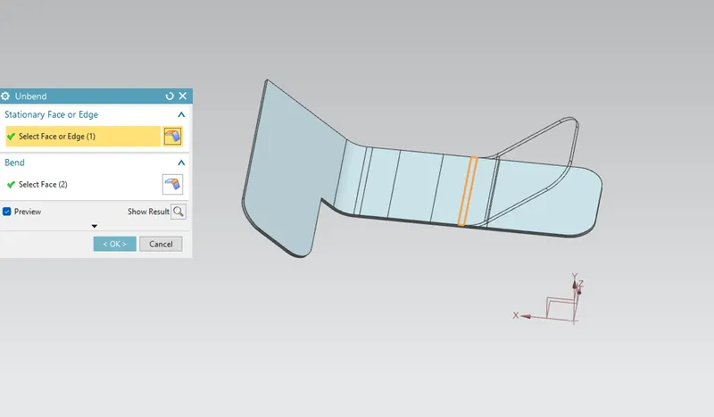
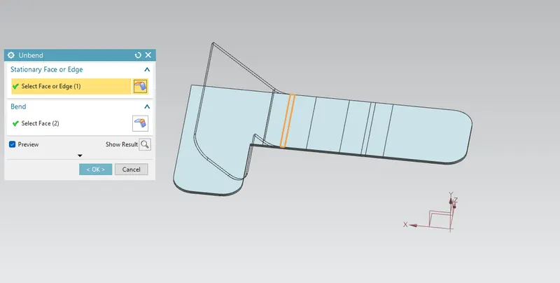
UNBEND:
This command is used to unbend the sheet metal. The punching & drilling operation can be performed by only flat planes only.
BEAD:
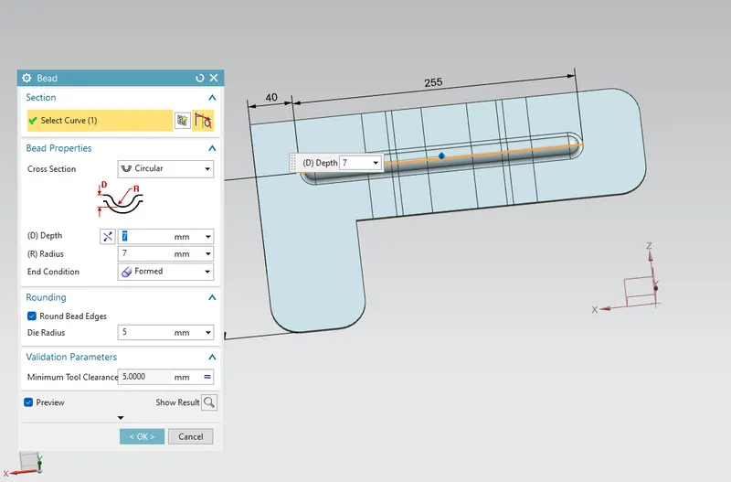
Bead is created to shape according to the sketch in the required direction with a required punch.
It is used to make bends on surfaces.
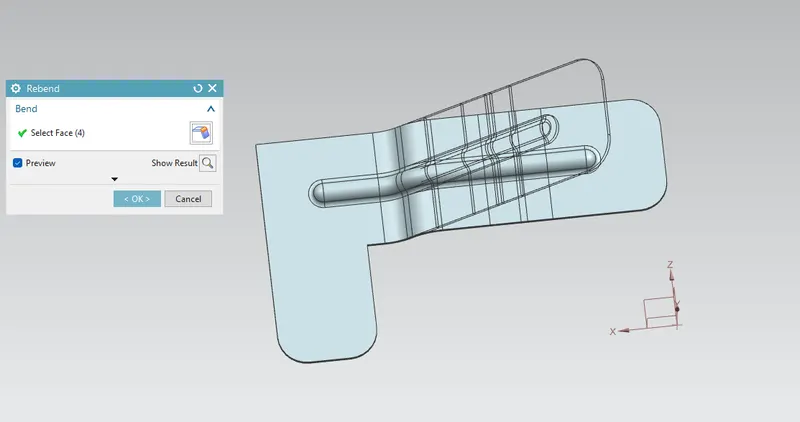
REBEND:
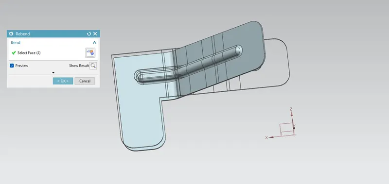
It is used to make an original shape to a sheet metal body by using the rebend.
Rebend is used to bend from the unbend parts.
HOLE:
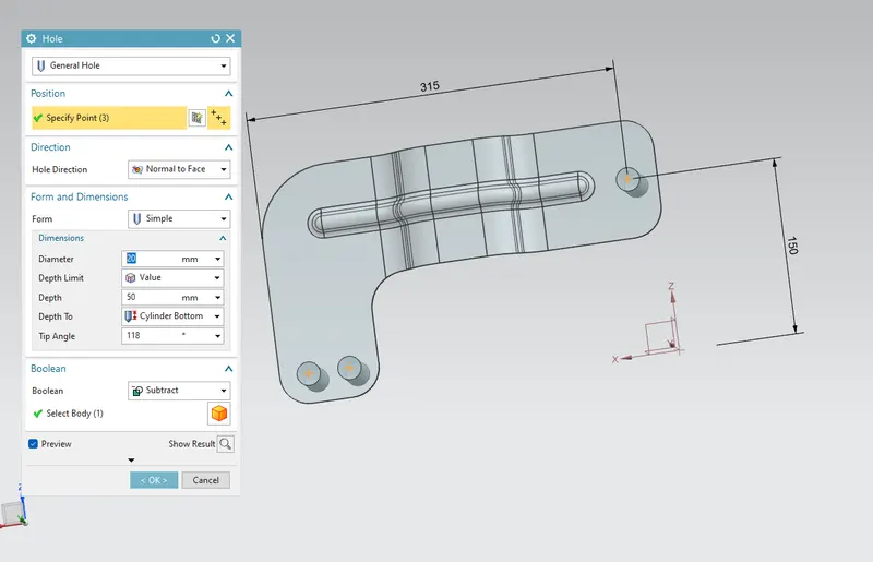
The hole can be created simple, with a screw clearance hole and a fit.
set the depth limit option to through the body.
It is used to create a hole in the sheet metal body.
FLAT PATTERN:
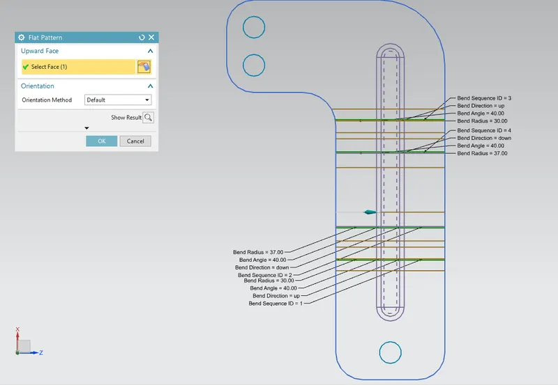
Select the central face of the metal sheet and validate.
Flat-pattern is the representation of the entire sheet metal component.
It removes the possible such as interference or collision within the same component
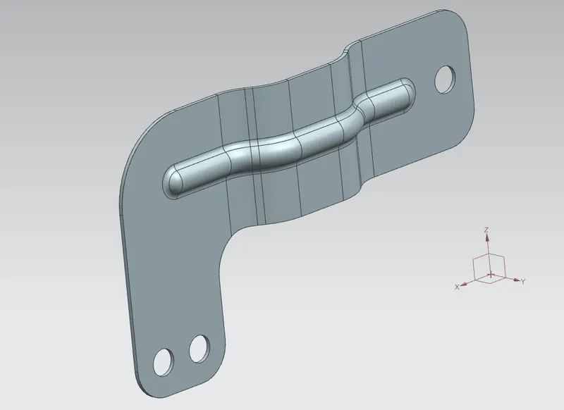
ISOMETRIC VIEW:
FRONT VIEW:
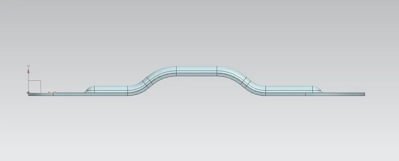
SIDE VIEW:
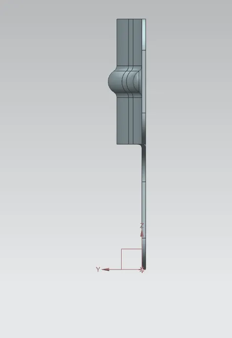
TOP VIEW:
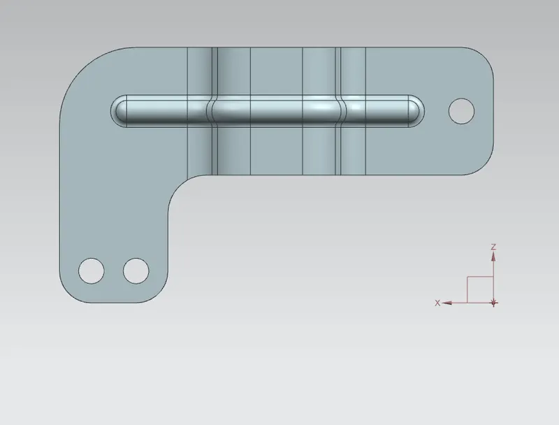
BOTTOM VIEW:
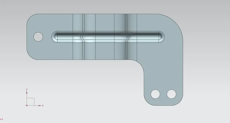
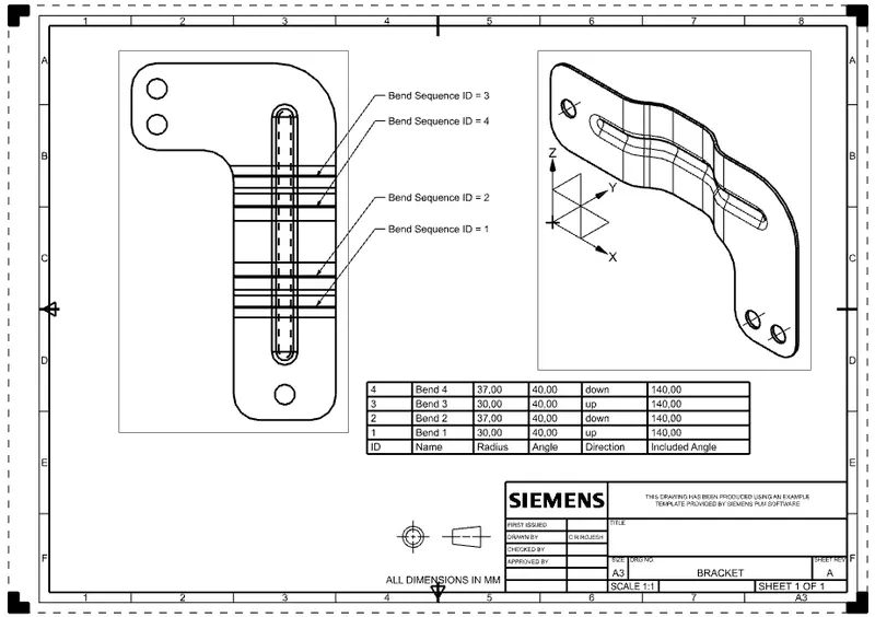
DRAFTING:
After the modelling, the manufacturing of the component a technical 2D drawing of the component with accurate dimensions or scales is denoted.
The draft is created with a scale of 1:1 and using A3 size. and add a new Base View.
In the Base View dialogue box, select the option Model View to use FLAT-PATTERN#1.
CONCLUSION:
This bracket has been completed by using the sheet metal application in Siemens NX CAD.
Then the required drawing sheet was created by using the draft application in the NX-CAD.
NX-CAD is used to maintain our desired design part and to follow the features are applied as per industry workflow.