Advanced Sheet Metal Design Using NX Cad Challenge_6_Bracket
SHEET METAL BRACKET
OBJECTIVE:- Sheet metal bracket using Sheet Metal features in NX CAD.
INTRODUCTION:- NX Sheet Metal provides a set of tools within the NX design environment that allows for simple and fast design of sheet metal parts, dependent on their material and manufacturing process, the most common of which is straight brake sheet metal forming.
DESIGN METHODOLOGY:- There are some step ot stages follows as shown as....
- Create a new sheet metal model as .prt file.
- Changing the parameters preferences accordingly.
- Create a sketch on certain plane.
- Use Contour Flange tool for creating sheet metal of certain length.
- Use Normal Cutout tool for modifies the sheet metal part.
- Round or chamfer a sharp corner of a tab and flange face by using Break Corner command.
- Flatten the bend and the material adjacent to the bend face by using Unbend command.
- Lift material along the contour of the sketch that simulates the stamping tool by using Bead command.
- Rebend command using to restores an unbend features to its previous bent state, along with any features addad after the unbend features.
- Use Local Radius Analysis, calculates geometric properties of selected point on curves, faces and edges.
- Use Measure tool, Calculates various measurement of the objects or sets of the objects.
- Add a hole to one or more solid bodies in a part with counterbored, countersunk and threaded by using Hole command.
- Drafting
Descrption:-
- Sketch:Creat a sketch in XZ plane and draw a contour with an certain dimesions.
- Adding a Solid Sheet:Exit the sketch mode, use the Contour Flange button for creating metal sheet of 3mm.
- Modification In Sheet: In that sketch, draw a profile symmetrical with respect to the x-axis which is coincide with the face of the rectangular sheet of certain dimesions for making a modified sheet metal by using Normal Cutout command, click on the Normal Cutout button, select the curve and then select the body.
- Breaking Corner for previous design: click the Break Corner button and create the round corner on edges where required.
- Unbending the Face: click the Unbend button, select as stationary face of the metal sheet for bending face one of its adjacent faces.
- Adding bead: draw a line on XY palne, Click on the Bead button, select the curve using sketch feature and select the bead properties along with validate parameter.
- Rebend: Click on the Rebend button select the bend faces respectively to restores an unbend features to its previous bent state, along with any features addad after the unbend features.
- Local Radius anlysis
- Adding Hole: Click on the Hole button, select the sketch tool and draw point on the face and after exit th sketch mode, select the hole properties with respect to hole parameter.
- Measure the distance between to hole for exact measurement analysis by Measure tool.
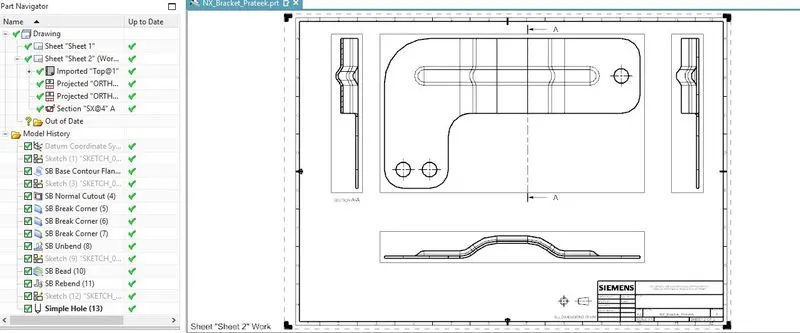
- Drafting, create a drawing sheet by using the Base view tool.
SCREENSHOT OF VIEWS of MODEL
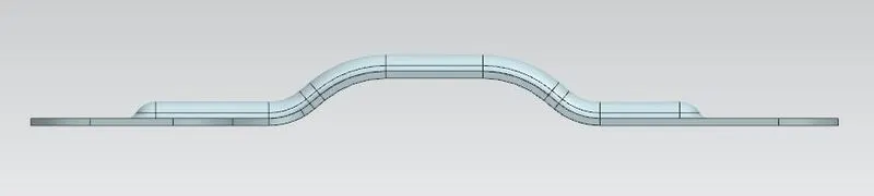
- Front View
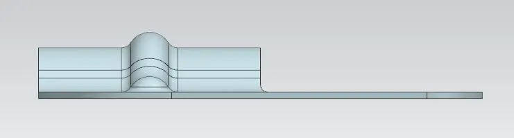
- Left View
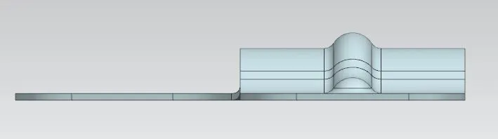
- Right View
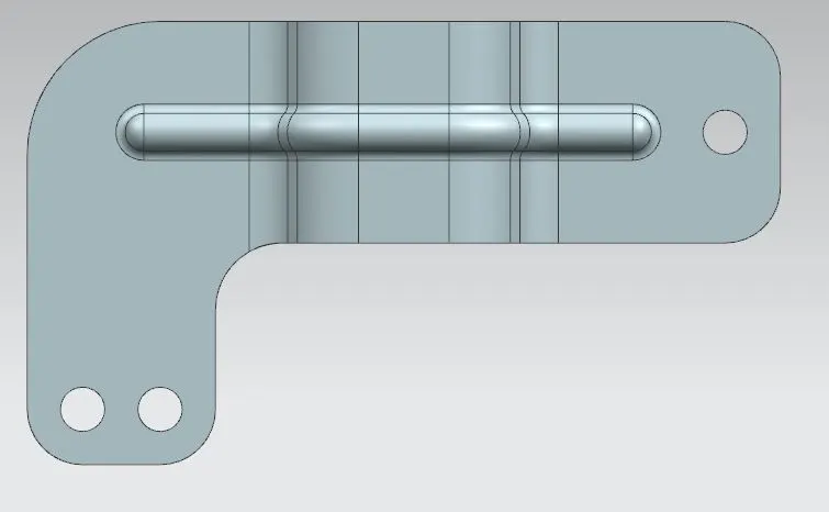
- Top View
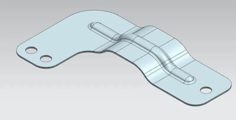
- Isometric View
- Drafting View
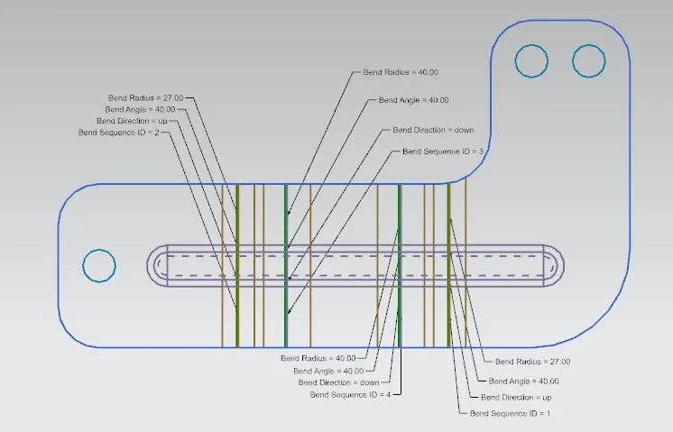
- Flat Pattern View
CONCLUSION:-NX sheet metal design software incorporates material and process information in sheet metalspecific modeling features: bends, flanges, tabs, cutouts, beads, dimples, louvers, corner and edge treatments, patterns and other formable features. You can also quickly convert solid models to sheet metal components, and create sheet metal parts that enclose other components.