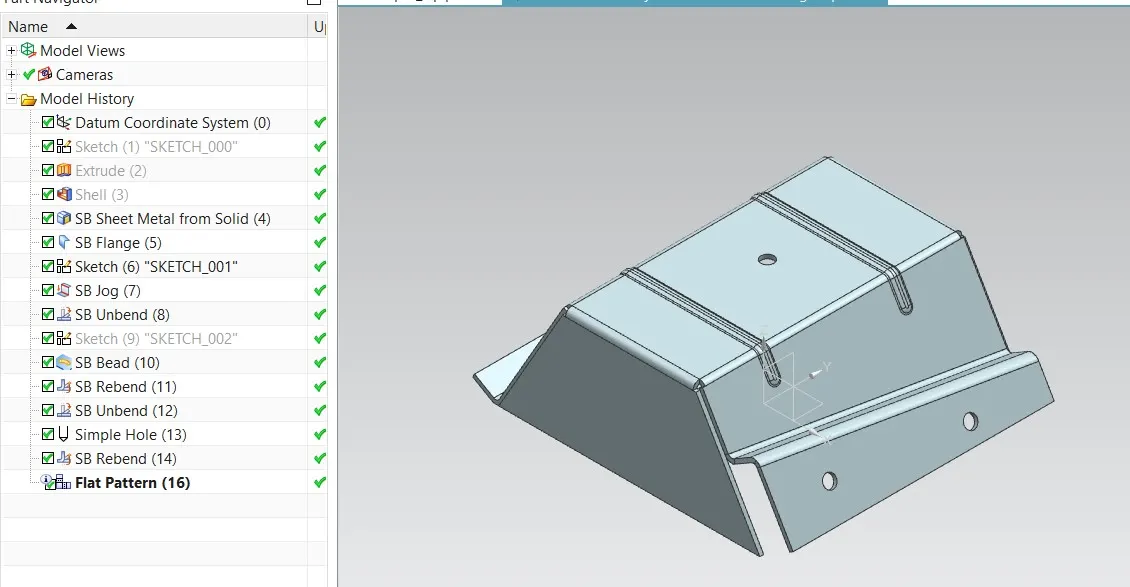
Advanced Sheet Metal Design Using NX Cad Challenge_5_Odd Shaped Enclosure
Advanced Sheet Metal Design Using NX Cad Challenge_5_Odd Shaped Enclosure
Objective : To design a Sheet Metal Design Using NX Cad sheet metal application.
Introduction :
NX Sheet Metal provides a set of tools within the NX design environment that allows for simple and fast design of sheet metal parts, dependent on their material and manufacturing process, the most common of which is sheet metal forming.
Description :
Extrude: Creating a features by extruding the sketch.
BEND : Bends sheet metal model through a line.Modified the model by bending material.
Flange :Ads flange on an edge and create a bend between two walls. The flange can only be made on a straight edge.To activate command.Click on command on (When sheet metal application activated.) “ Home => Bend Group => Flange”Activate command from “Menu => Insert => Bend => Flange”
Unbend : It allows all the bend to unbend sheet.It is necessary to choose the bend, it can also to box select all the bend at once.
Hole : Hole feature is just like the same as the put a hole in the sheet eith respective measurements of sktch.
Dimple: Dimple in the sheet metal which will make more rigidity and stregth to that flat sheet component.
Beads: Beads are the features added in the sheet metal to increase the stffness of the component.
Flat pattern: Create a flat pattern from the formed sheet.
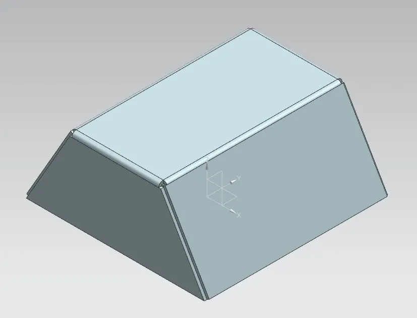
Fig-1
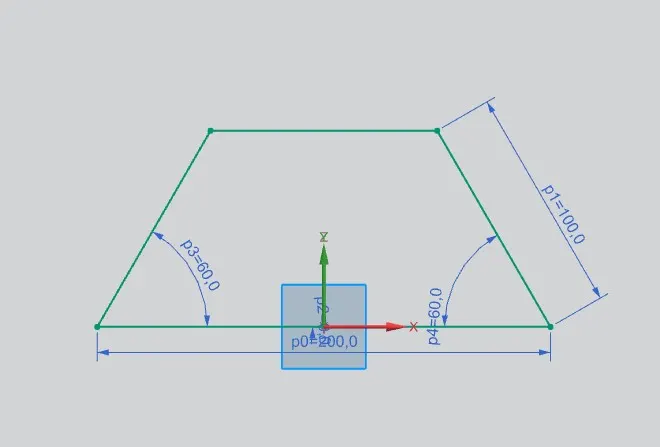
Fig-2
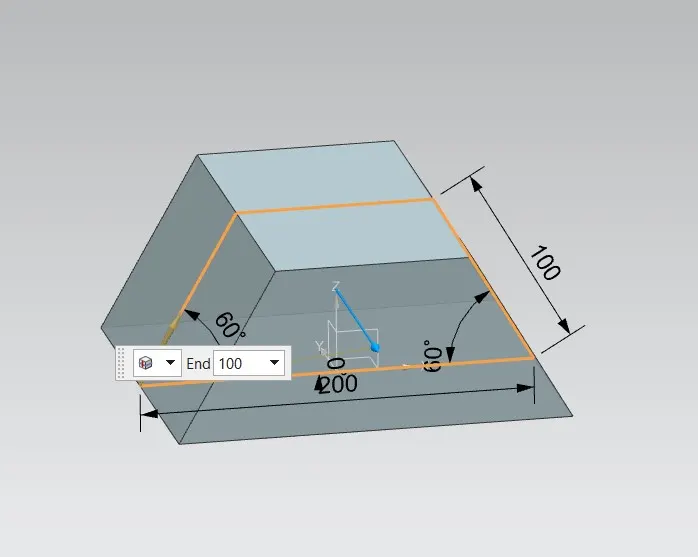
Fig-3
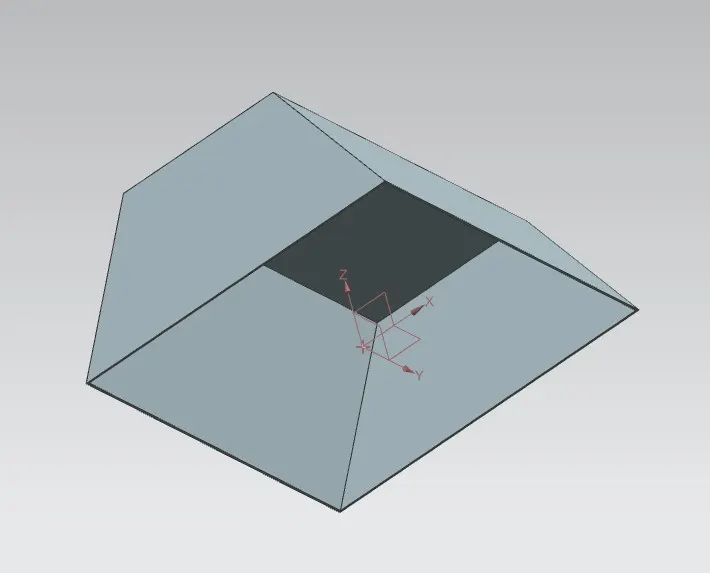
Fig-4
Add a features such as flanges,jog or bend.
Add flange select the edge which want to be flange and the length 20mm with angle 90 degree.
Length references : inside, Inset : material inside.
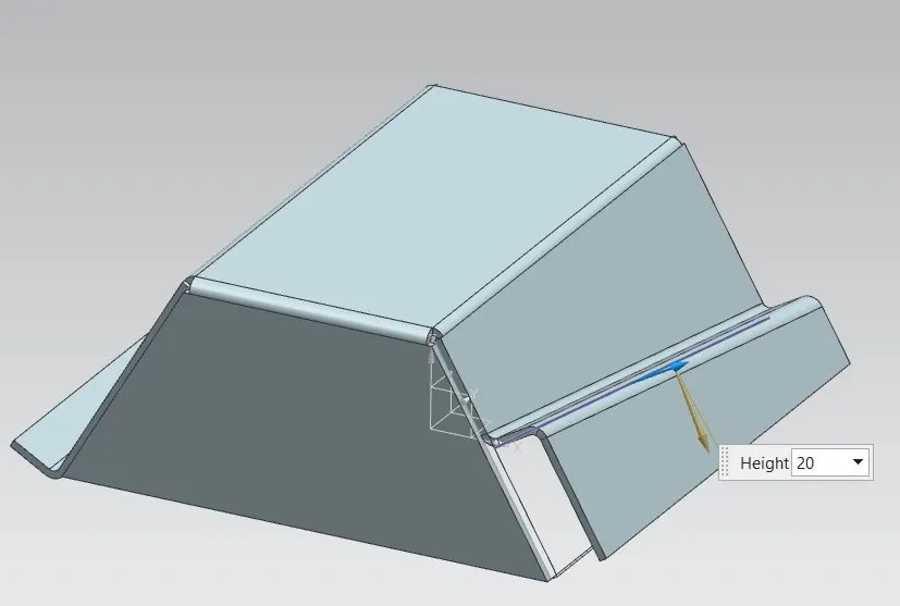
Add a jog for thet want a sketch. so draw a appropriate sketch for jog where to be it.
Jog the selected curve with the length 20mm with angle 90 degree.
Length references : inside, Inset : material inside.
Fig-5
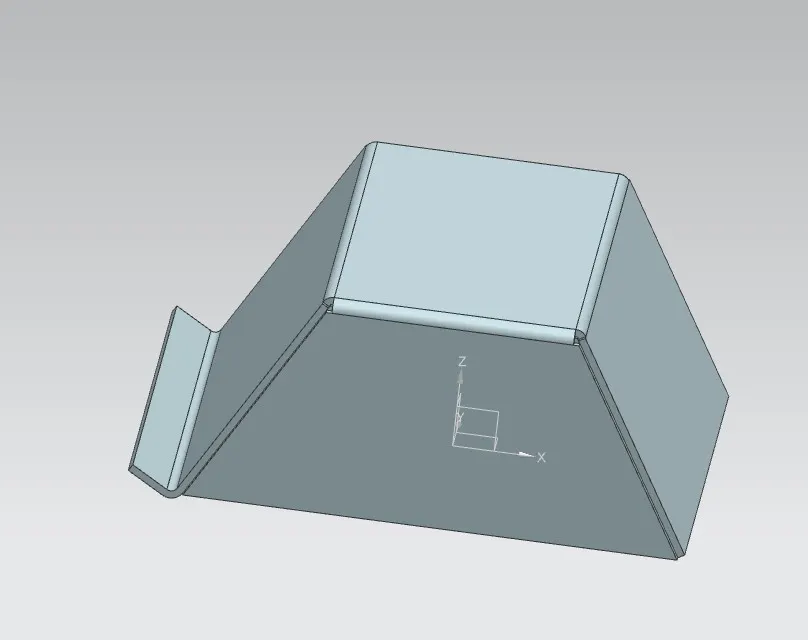
Fig-6
Ubend the sheet metal to add features such as dimple, hole, beads etc...
Select the curve for the bead. The cross section : circular.
Depth : 3.0 radius : 3.0
To create a hole select the point to where to be hole. Add the points it.
Give the general hole with the diameter of 10mm.
Rebend it.
Fig-7
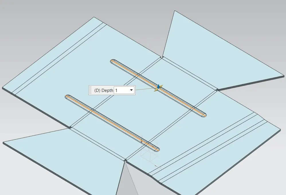
Fig-8
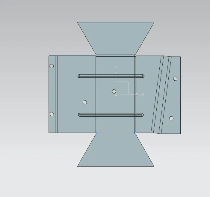
Flat Pattern
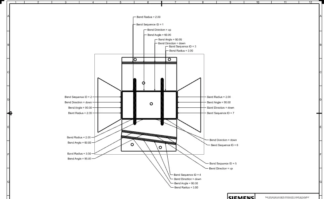
Views
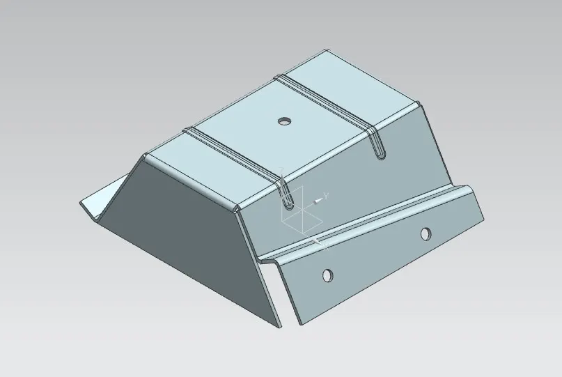
Isometric view
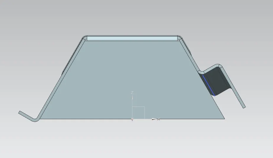
Front view
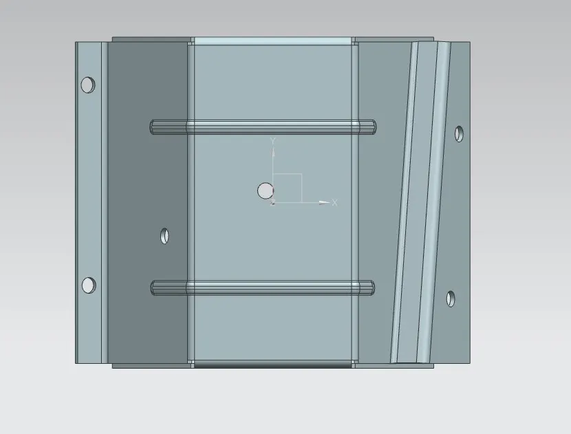
Top view
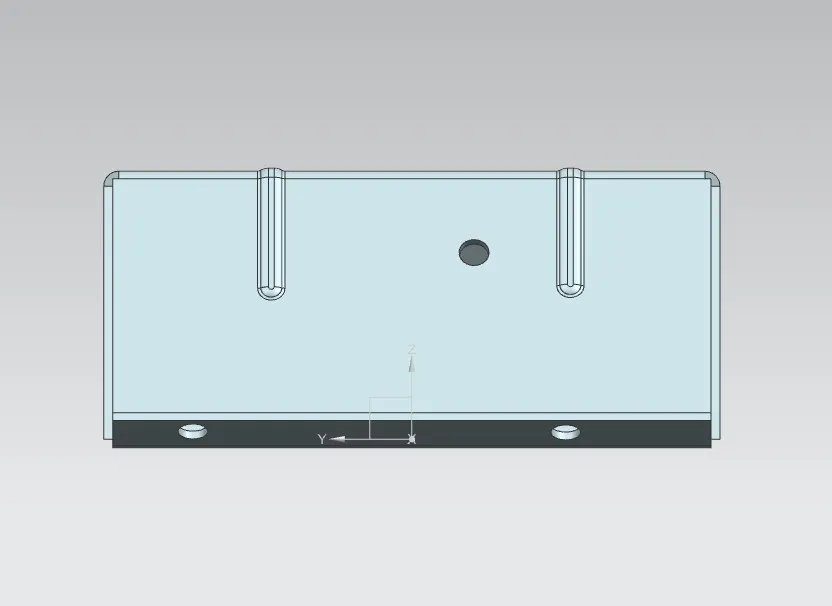
Side view
Structural tree