Advanced Sheet Metal Design Using NX Cad Challenge_5_Odd Shaped Enclosure
ODD SHAPED ENCLOSURE
OBJECTIVE
To design an odd shaped enclosure and create a draft of it using Siemens NX Sheet metal application.
INTRODUCTION
Sheet metal is metal formed by an industrial process into thin, flat pieces. Sheet metal is one of the fundamental forms used in metal working, and it can be cut and bent into a variety of shapes. Countless everyday objects are fabricated from sheet metal. Thicknesses can vary significantly; extremely thin sheets are considered foil or leaf, and pieces thicker than 6 mm (0.25 in) are considered plate steel .
Sheet metal is available in flat pieces or coiled strips. The coils are formed by running a continuous sheet of metal through a roll sitter.
NX CAD Sheet Metal Module is used for Creating fast, accurate flat patterns is the goal of any organization that manufactures products which contain sheet metal parts. NX Sheet Metal provides a set of tools within the NX design environment that allows for simple and fast design of sheet metal parts, dependent on their material and manufacturing process, the most common of which is straight brake sheet metal forming.
With NX Sheet Metal, formed and unformed representations of the parts are created closely following the industry workflows and best practices for bending calculations, tooling, and sheet metal features. The value lies in improving quality and reducing cost of sheet metal parts by producing an accurate sheet metal pattern as the correct input for part manufacture, whether internally or to a supplier.
DESIGN METHODOLOGY
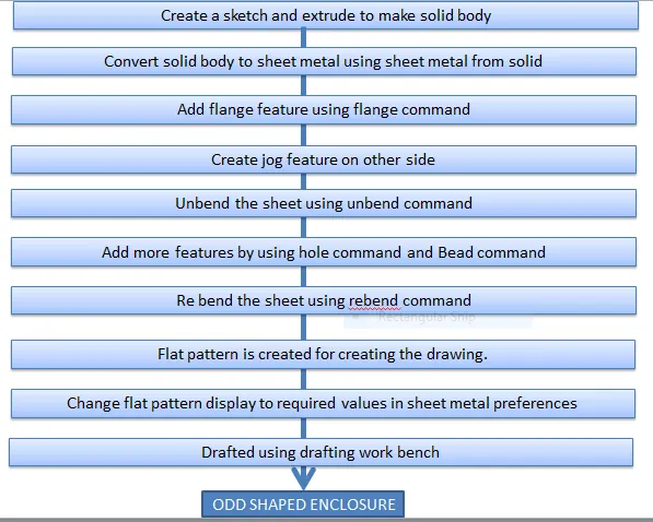
FEATURE DESCRIPTION
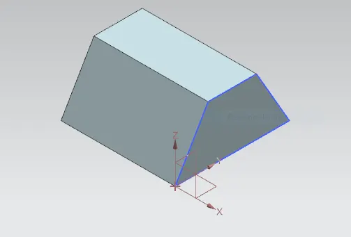
EXTRUDE
This command creates a solid body by extruding a sketch along a vector by a thickness value or by adding material to a plane face.
SHEET METAL FROM SOLID
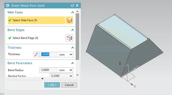
This command is used to convert a non-Sheetmetal part to a sheet metal in order to perform the sheet metal operations like unbend, flattening etc.
In NX, solid models and imported non-sheet metal parts could also be converted to sheet metal parts.
FLANGE
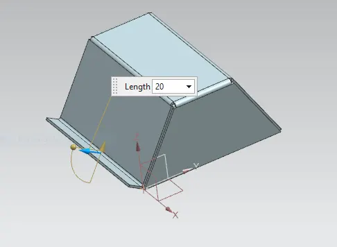
Adds flange on an edge and create a bend between two walls. The flange can only be made on a straight edge.
JOG
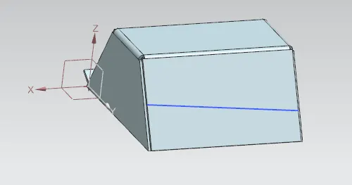
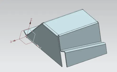
Lifts one side of the sheet metal part through a defined line. Ads flange between the stationary side and the lifted side.
UNBEND
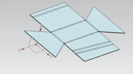
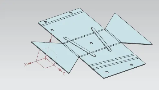
It’s an command used to flatten the created 3d model taking one face as a stationary face.This feature is used to unbend the adjacent bends and flatten them.
BEAD
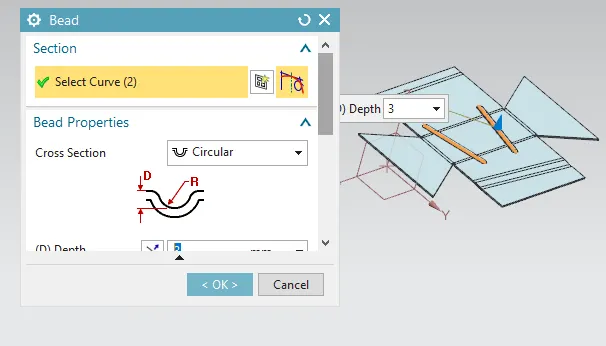
It is also type of projection to deform the shape at a certain point with reference to sketch and also giving strength to the material.
Beads are the features added in sheet metal components in order to increase the stiffness of the component.
HOLES
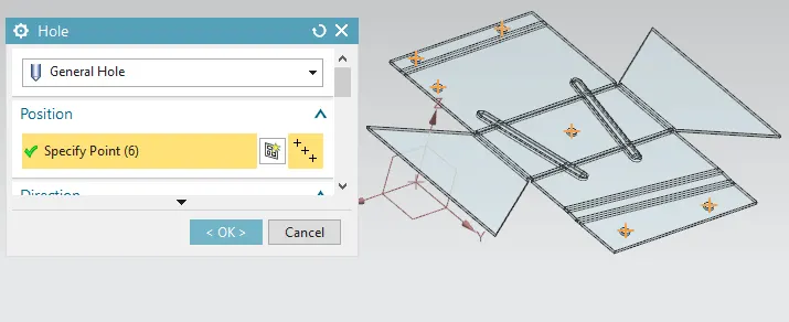
It adds a hole to one or more solid bodies in a part or an asembly with options for counterbored, countersunk and threaded. Here six simple holes are created on the unbent surface with a diameter of 10mm. It can be used to make customized or standardized holes along with a defined point or path. The dept of the hole can be controlled.
REBEND
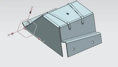
Restores an unbend feature to its previous bent state, along with any features added after the unbend feature.
FLAT PATTERN
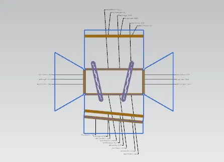
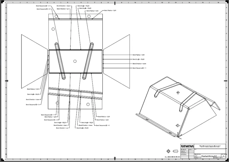
It creates a flat pattern feature from the formed sheet metal part. The user chooses this command to create a flat view of the sheet metal after unbending all the sides and faces. This view can be used in drawing the flat pattern along with the bend radius and other dimensions.The flat pattern ensures the ability to cut the sheet metal out of the raw sheet metal plate. It removes the possible errors such as interference or collision within the same component.
DRAFTING
After the design is complete, the execution or the manufacturing of the component requires a technical drawing of the component with the provided scale and with accuracy.
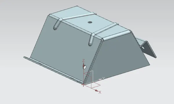
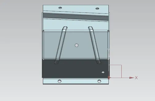
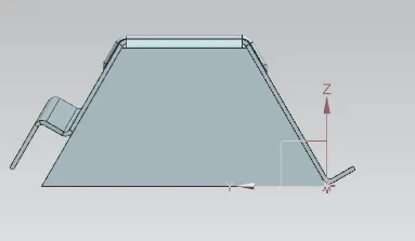
VIEWS
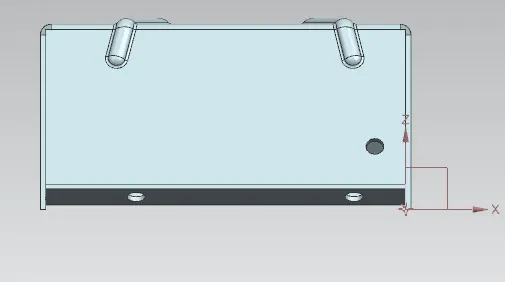
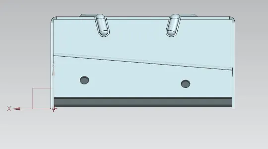
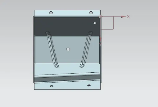
CONCLUSION
ODD SHAAPED ENCLOSURE is dwsigned and a draft is created using Siemens NX .