Advanced Sheet Metal Design Using NX Cad Challenge_5_Odd Shaped Enclosure
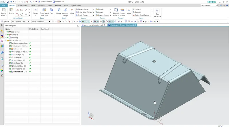
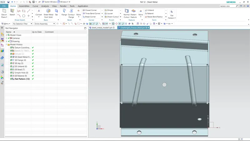
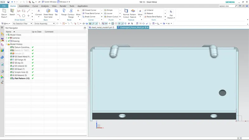
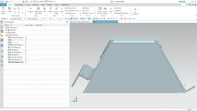
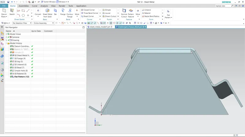
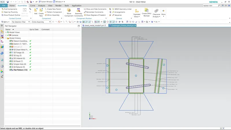
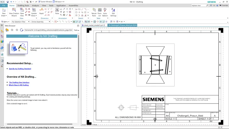
TITLE- create enclosures with odd shapes or angles
OBJECTIVES-To creat sheet metal from solids and reat the stiffened fetures.
INTRODUCTION-In this tutorial we will learn the recommended workflow procedure to design a ‘Sheet Metal part for odd shapes’ using Siemens NX Sheet Metal Application.
- METHODOLOGY-
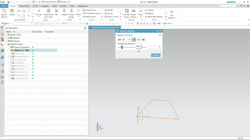
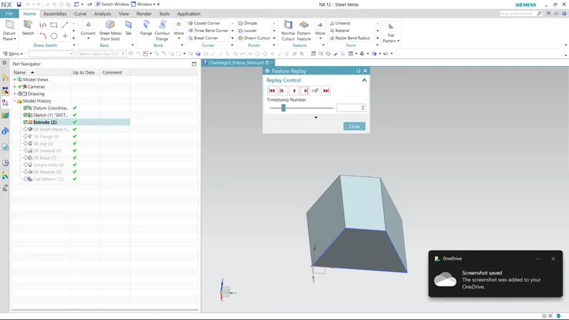
- First I did the drawing in YZ plane.
- I did extrude then.
- Then I applied the 'sheet metal from solid' coomand for convert a sheet metal from the solid.
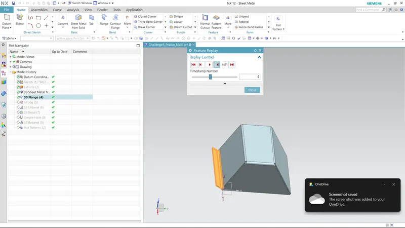
- I creat a flange in the left side of the sheet metal.
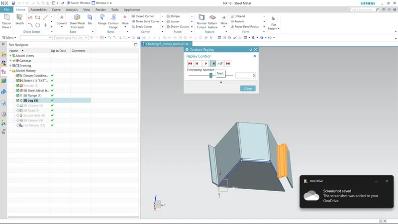
- I creat a jog using a sketch what I have done already.
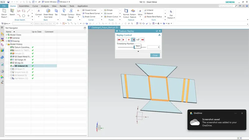
- then I unbend the part.
- After unbend I did beads and holes on the upper surface of thesheet metal.
- then I rebend the unbend.
- At last I did the flat pattern command and creat a drawing sheet which are shown in the above.
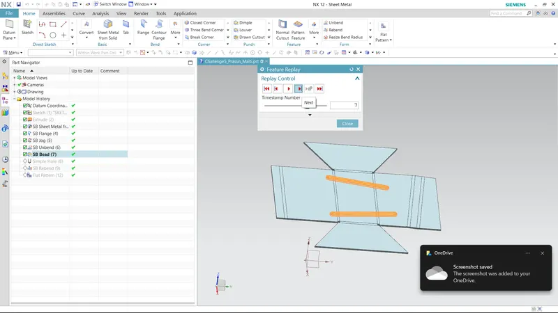
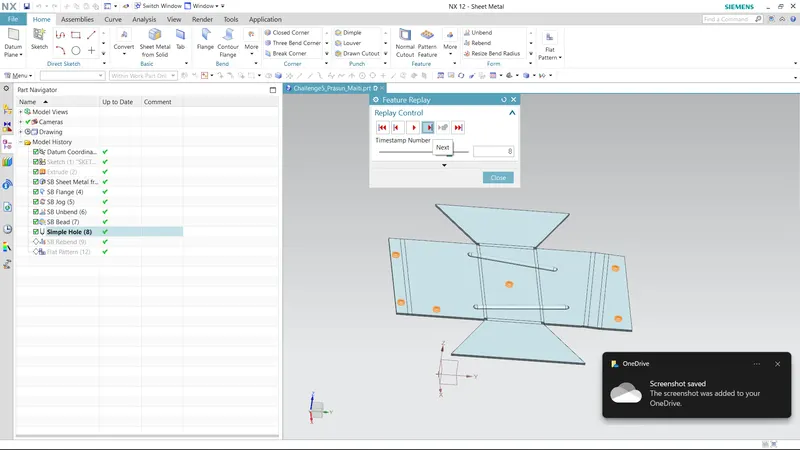
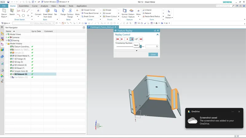
FEATURE USED-
- EXTRUDE-Extrude are used to creat a 3d from the 2d sketch.
- SHEET METAL FROM SOLID COMMAND-This command is used ato creat a sheet metal from a define solid body.
- FLANGE-Flange command is used for creating flanges on the sheet metal edges.We can't use flange command on a solid body or we can't creat flange ona solid.
- JOG-Jog command is used to creat a parallel flange on a edge of sheet metal by cutting some of the sheet metal.
- UNBEND-Unbend command I used to get a formed sheet metal nto it's flat position. Generally when we want to creat some features like beads, dimple, holes, etc. We used the Unbend to do sheet metal into a flat sheet.
- REBEND-Rebend is use to get the Unbend sheet metal into it's last position.
- FLAT PATTERN-Flat pattern is used to screat a drawing sheet or 2d image with the dimension analysis, and about the all features.