Advanced Sheet Metal Design Using NX Cad Challenge_5_Odd Shaped Enclosure
Designing of an Odd Shaped Enclosure using NX
OBJECTIVE
In this project a sheetmetal will be generated from the input solid body and then sheetmetal features will be used on it to design the Odd Enclosure.
DESIGN METHODOLOGY
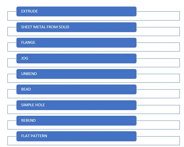
The steps that are used to make the desing of the Odd Enlcosure is shown below through a flowchart.
PROCEDURE
1. As the main of this project is to make sheetmetal from a solid body and then perform sheet metal operations on this sheet, first a solid body is made with the help of an Extrude command.
Extrude - This command is used to add material with more thickness in a certain diresction with the help of a base sketch.
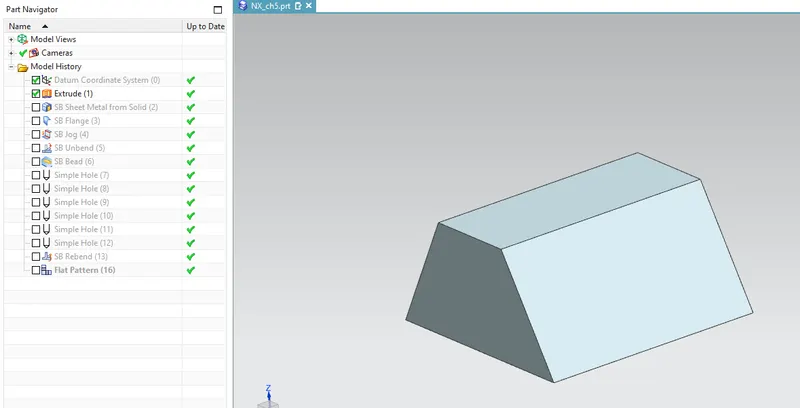
The above image shows the solid body created in this project.
2. The next step is to generate the sheet metal from the above solid body, for this purpose Sheetmetal from Solid feature is to obtain this.
Sheetmetal from Solid - In this feature first the web faces upon which we want to hace the sheet metal material and then bend edges need to be selected appropriately to obtain the sheetmetal on top the solid body.
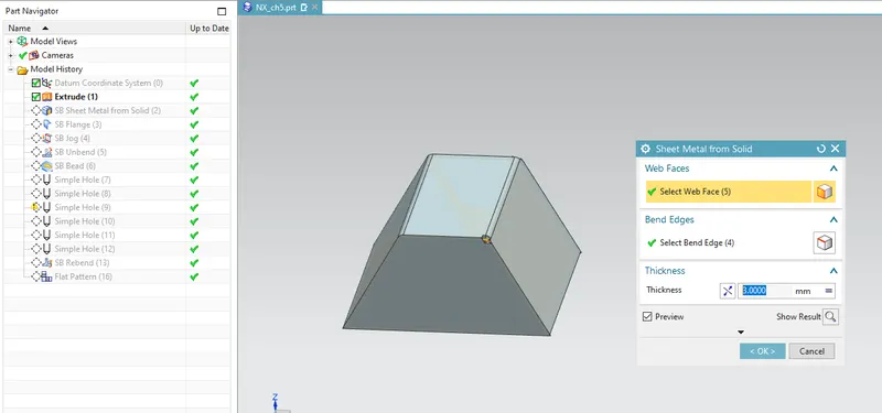
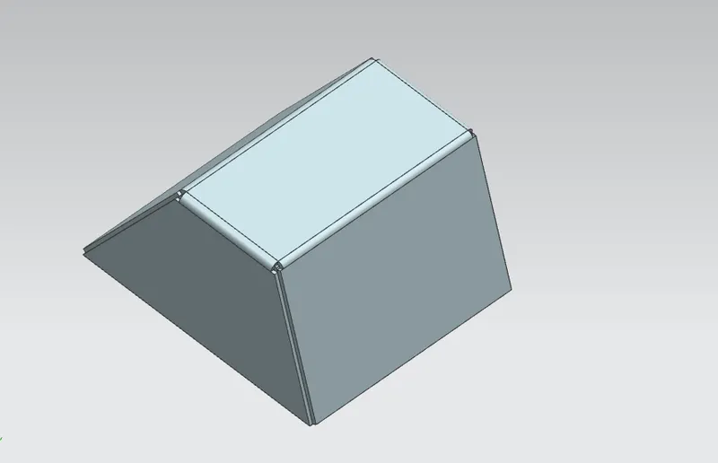
In the above image we can see that sheetmetal material is created on top of the solid body. The bending regions are generated automatically when the egdes are selected in appropriate manner.
3. As the sheet metal is prepared, next step is to perform sheet metal operations on the above material.
A Flange is first generated on the sheet metal by selecting one of the edge.
Flange - This feature is used to add a flat web at an angle to the planar surface. Flanges consists of web and bending radius which is already defined in the global parameters.
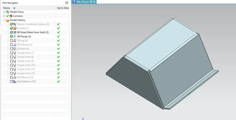
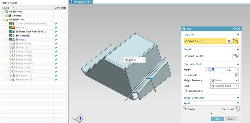
4. A Jog is then designed on one of the sides of the sheetmetal.
Jog - This feature is used to lift material from one of the side of the sheetmetal by drawing a line in the sketch, a flange is generated in between the two faces and then height of the flange is given.
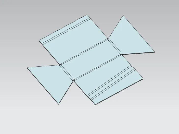
5. Unbend feature is used to see the flat body of the sheet metal.
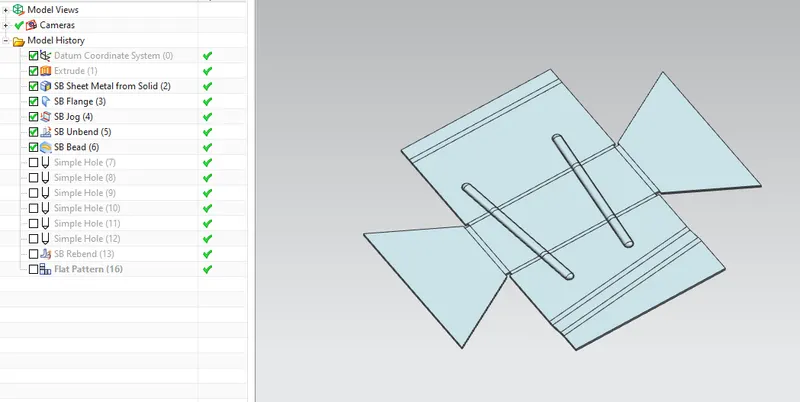
6. THe next feature which is used is beads which are designed on the above unbended surface of the sheetmetal. This operation is also performed with the help of stamping tool in the manufacturing industry.
Bead - this feature is used to lift material along the contour a sketch. It provides strength to the sheetmeal.
7. Simple Holes are then generated on the above sheetmetal to add this feature.
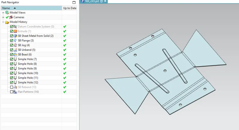
8. After all the features are added the sheetmetal is again rebended to see the original shape of the generated sheetmetal.
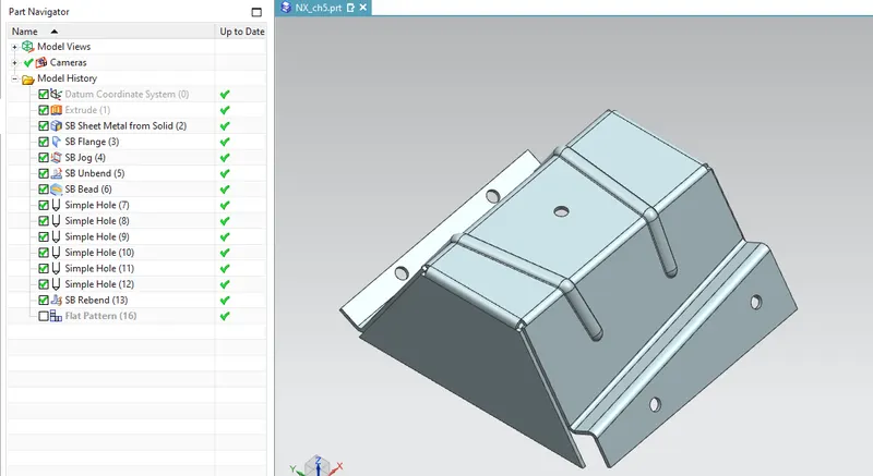
In this above image we can observe that the required sheetmetal is generated with the help of the solid body and then the sheetmetal operations can easily be performed on it.
Different views of the above obtained sheetmetal are:
1. Isometric view
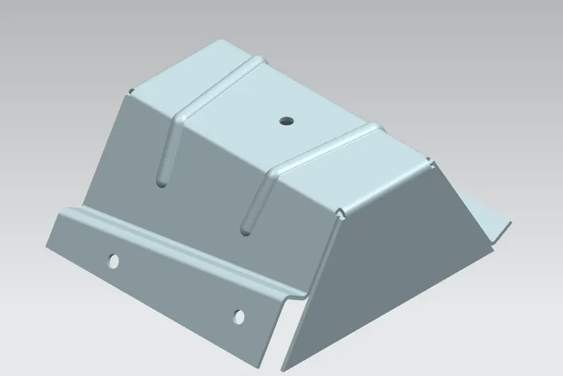
2. Front view
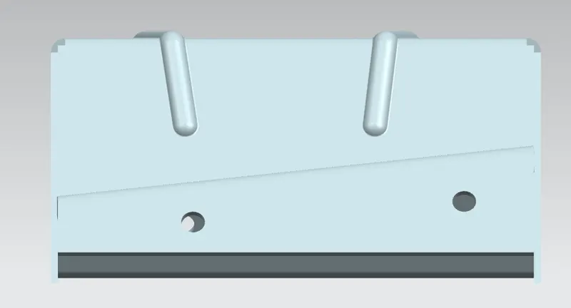
3. Top view
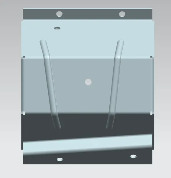
4. Bottom view
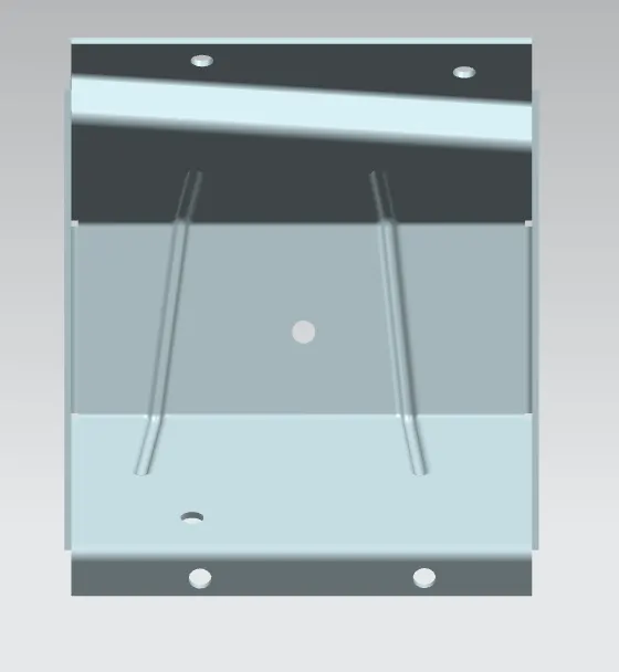
5. Side view
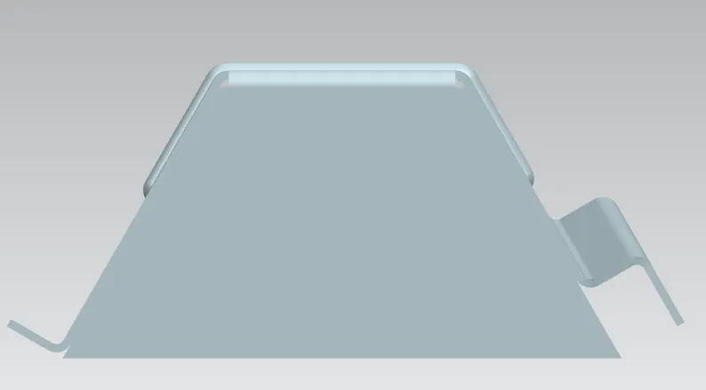
DRAFTING
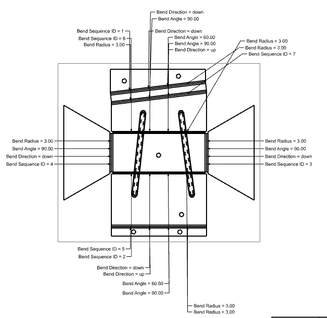
In order to provide the specifications of the above sheet metal, Flat Pattern feature was used and then it is drafted on the drawing sheet.
CONCLUSION
1. The solid body was converted into the sheetmetal .
2. The sheetmetal featues were also used on the generated sheetmetal.
3. A draft is generated which mentions all the specifications of the generated sheetmetal.