Advanced Sheet Metal Design Using NX Cad Challenge_2_Box Assembly
Objective : To create a box assembly Using the sheet metal Apllication in NX CAD.
Design Methodology :
The Box Assembly of this project is created by using these features. Tab,Flange,Normal Cutouts,Beads,Dimple,Hem & ETC. Part is constructed gradualy step by step. & to reduce the no of features in part assembly time to time mirror command is used.
Commands Used :
Sketch, Tab, Normal Cutout, Flange, Break Corner, Unbend, Rebend, Flat pattern, Hem.
Steps followed for creating the Part :
Sketch : Sketches are the foundations for creating any part from scratch. I this project I have to create a base for further creation so i have used the sketch command & created a rectangle of required dimensions.
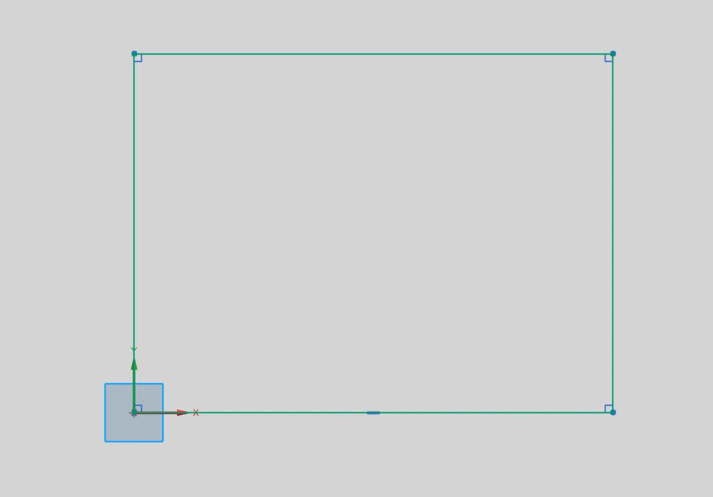
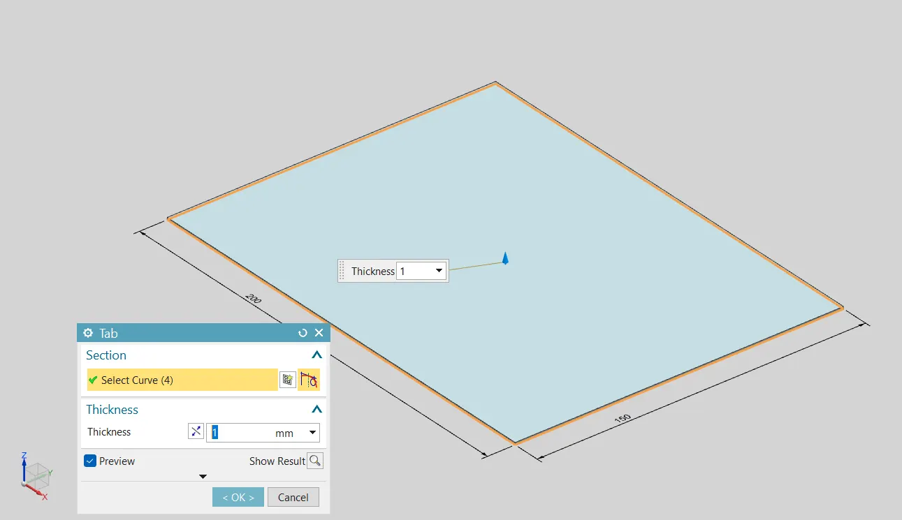
Tab : The 2D sketch is converted into a 3D base using the Tab command. This command generates a solid sheet surface of given thickness. which will be the Base of further Creations.
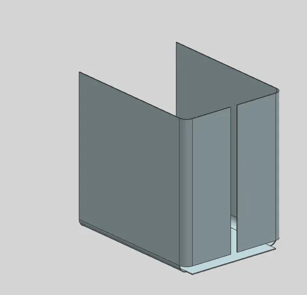
Flange : By Using flange command We have created the closed Surface enclosure on the 3 sides. We are Creating only the right side of the box in comming steps we will mirror the created part to achieve a whole body.
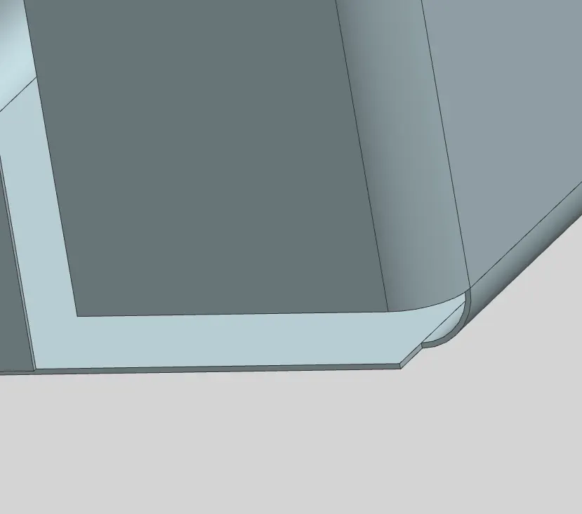
Closed Corner : This Command Fills the gaps between the Edges & gives a closed surface between the edges.
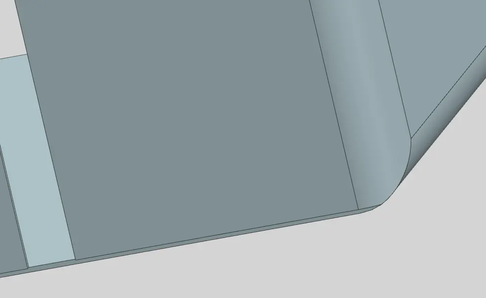
Flange : By using Flange command we have Created the joining element of both the sheets to provide the strength to the box.
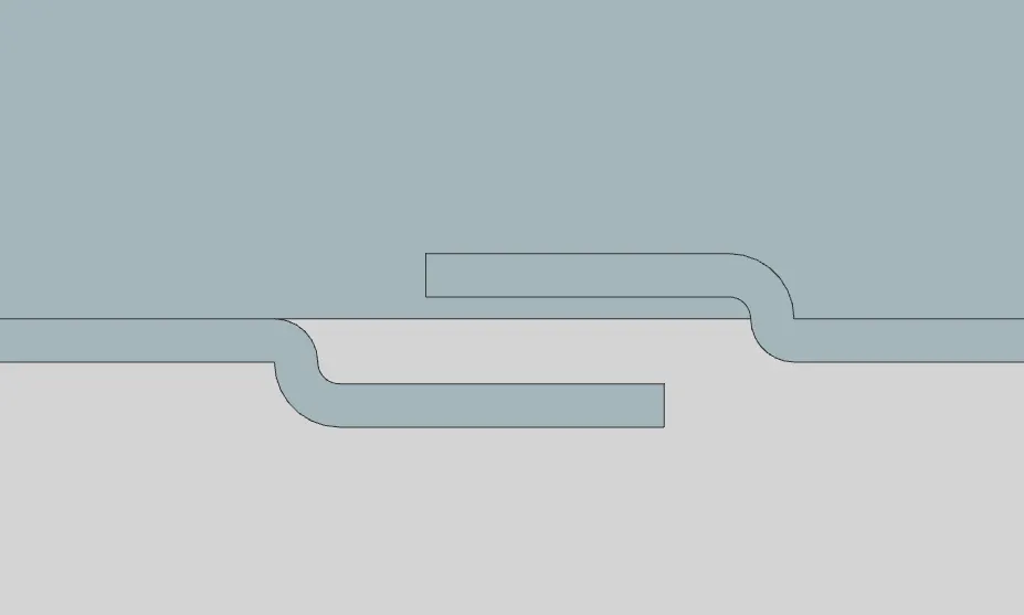
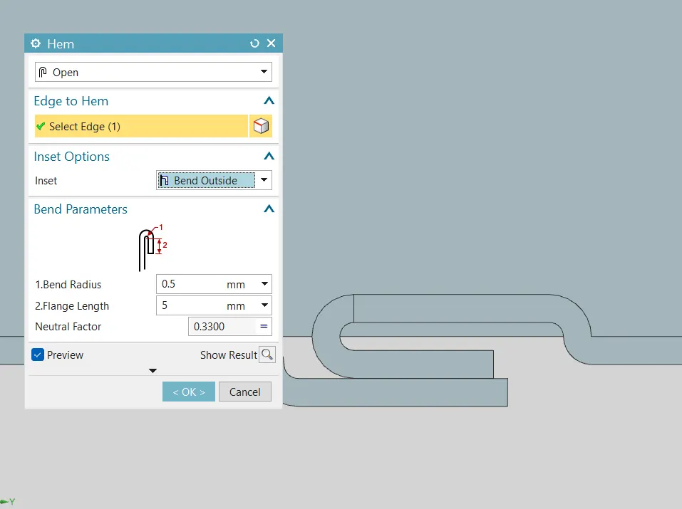
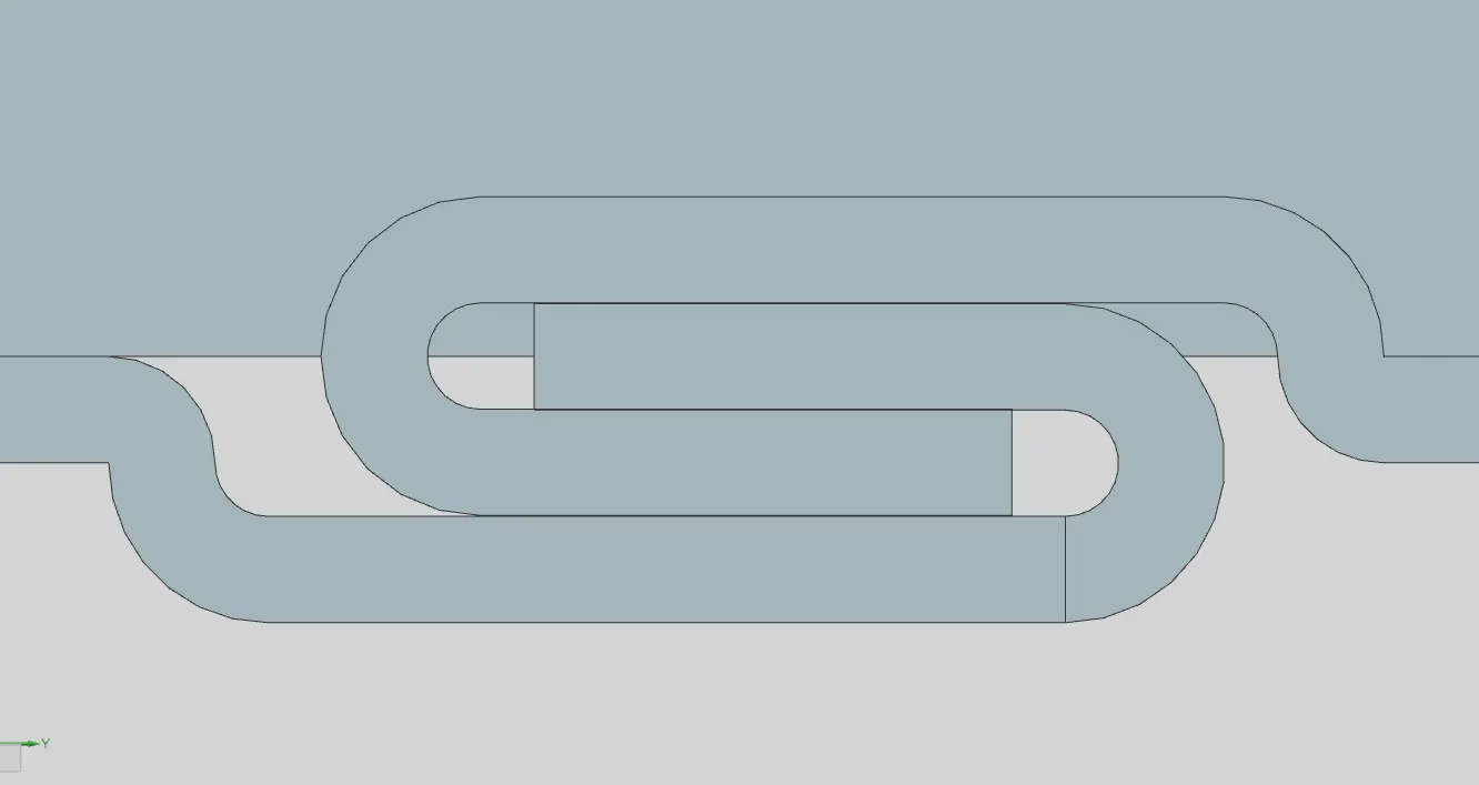
Hem : By using heg command we have created open hem to interlock the two sheet bodies with each other. the Hem is created for the Required Dimensions.
Dimple : Dimple command is used to created surfaces which are Elevated or deprevated from the Base Surface. The main Reason of using Dimples on Any sheet metal parts is the Embossments provide strength to the part.
Bead : Beads are created on the bottom Surface of the box. Along with other Dimples.
Hem : Closed Hems Are created around the top corner of the Box to avoid the sharp corners and to provide the Girp for top lid while closing the box.
Tab : Top lead is created through the sketch surrounding the box corners. then tab Command is used to thicken the sketch.
Flange : The lid Closure surface are created using the Flange command.
Tab: Hinge base is created on the one side of the box With the help of sketch. which will be fixed to the box.
Flange & Hem : an elevated surface is created to provide room for creating hollow cylidrical shape using Hem Command.
Normal Cutout : This command is used too cut the Hinge sheet. Cutouts are done with the help of Sketches of required dimensions.
Rebend & Mirror : Then the Sheet is rebended to its previous state. And the Hinge is Mirrored to the Other side of the Box.
By Following the Similar steps Used for creating a Hinge on Box we create A Hinge on the Lid.
Final Part