Advanced Sheet Metal Design Using NX Cad Challenge_2_Box Assembly
TITLE : Advanced Sheet Metal Design Using NX Cad - Box Assembly
OBJECTIVE –
- Understanding Advanced sheet metal design.
- Modelling of sheet metal Box Assembly on SiemensNX.
- Create uniform thickness sheet metal parts using features such as tabs, flanges, cut-outs, dimples, beads etc.
INTRODUCTION –
The sheet metal application provides an environment for the design of sheet metal parts used in Machinery, Automotive, Aerospace, Marines, etc. Sheet metal is a metal such as aluminium, brass, titanium, nickel, tin, and copper processed into thin flat pieces like foils, leaves, and plates.
Sheet metals are a valuable asset to industries and low volume production. Many industries are adopting the concept of Design For Manufacturability, or more commonly known as DFM. In sheet metal design industries, DFM helps avoid technical errors in the design process to improve the manufacturing lead times based on the sheet metal thickness chart and preceding calculations.
DESIGN METHODOLOGY / APPROACH –
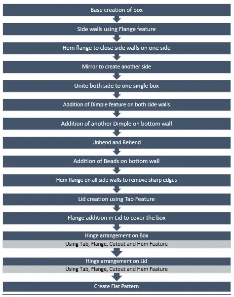
DESIGN DESCRIPTION –
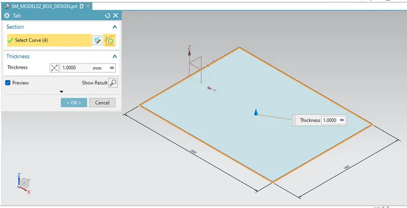
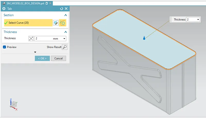
BASE FEATURE – TAB
Creates a base feature by extruding a sketch along a vector by a thickness value or adds material on a planer face. Additional planar sections can be added to generate bends as part of the base feature. adds a flat flange at an angle to a planar face and adds a bend between the two.
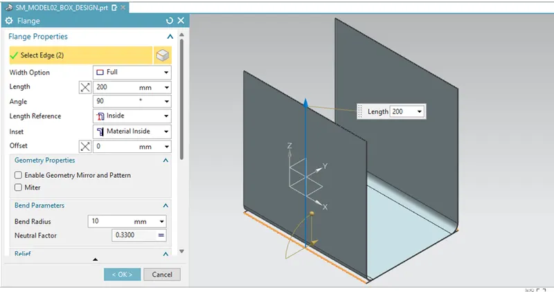
FLANGE FEATURE –
Adds a flat flange at an angle to a planar face and adds a bend between the two.
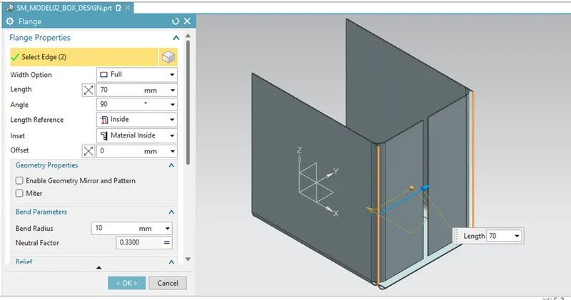
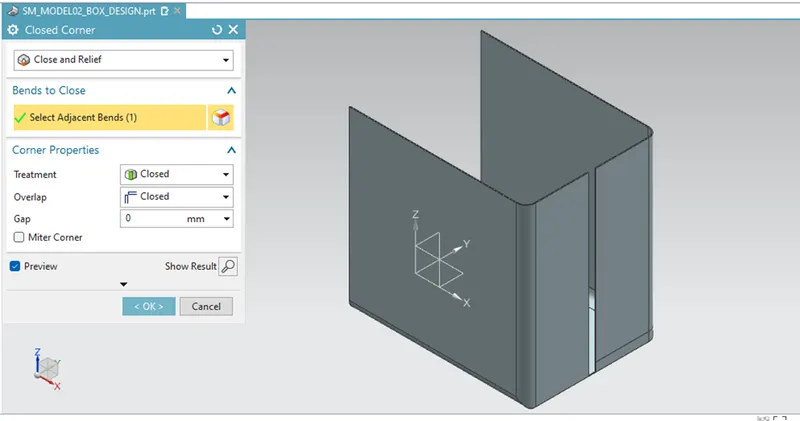
Closed Corner –
Closes the corner where two adjacent edges meet by extending the bends and flanges.
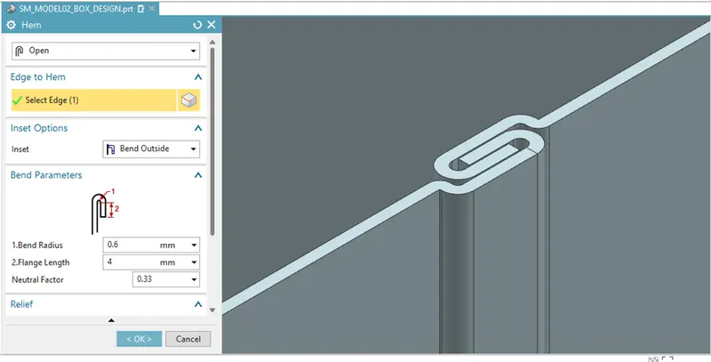
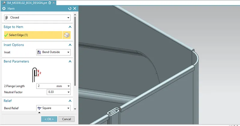
HEM FLANGE –
Modifies the model by folding the edges of sheet metal flange over onto itself for the purpose of safe handling or to increase edge stiffness.
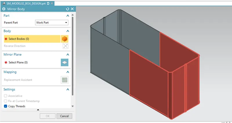
MIRROR BODY –
Copies a body and mirrors it across a plane.
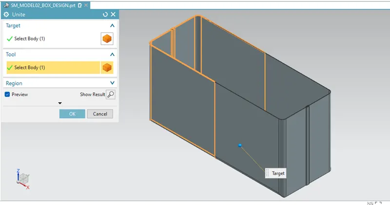
UNITE –
Combines the volumes of two or more solid bodies into a single body.
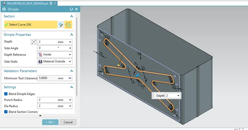
DIMPLE – (SIDE WALL)
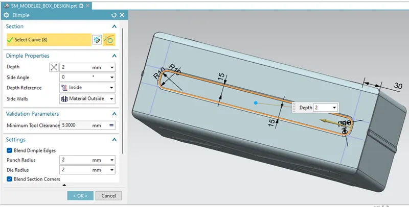
Lifts an area of a model inside a sketch that simulates a stamping tool.
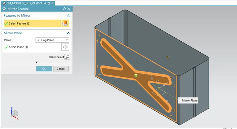
MIRROR FEATURE –
Copies a feature and mirrors it across a plane.
DIMPLE – (BOTTOM WALL)
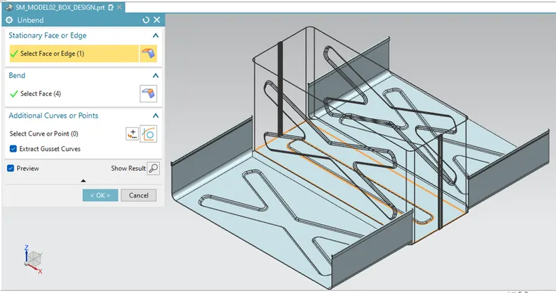
UNBEND – ( to add more sheet metal features )
Flattens a bend and the material adjacent to the bends.
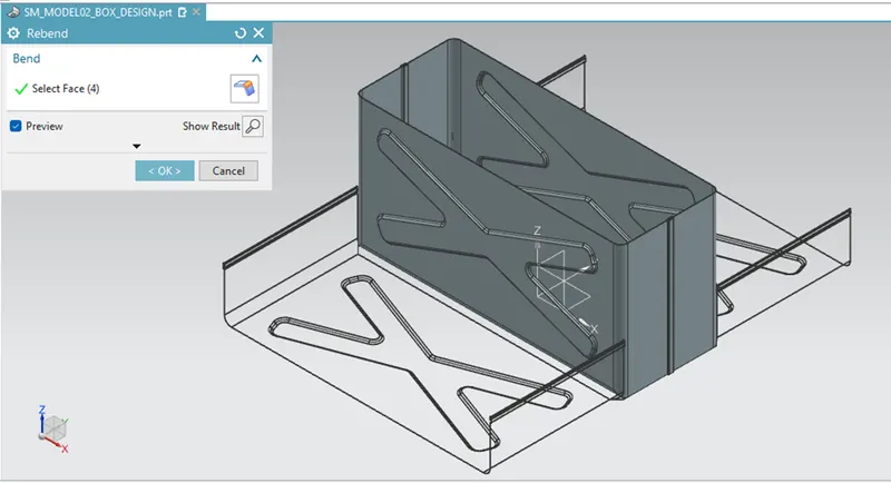
REBEND –
Restores an unbend feature to its previous bent state along with any features added after the unbend feature.
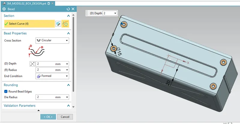
BEAD –
Lifts material along a contour of a sketch that simulates a stamping tool.
HEM FLANGE – (to remove sharp edges)
LID CREATION – (Using TAB feature)
HEM FLANGE – (To cover the box)
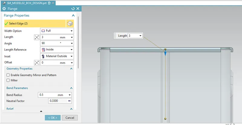
HINGE ARRANGEMENT – For Box
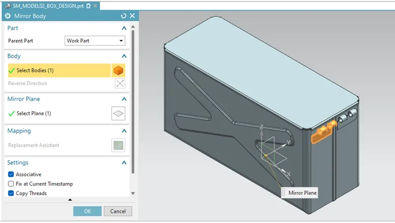
HINGE ARRANGEMENT – For Lid
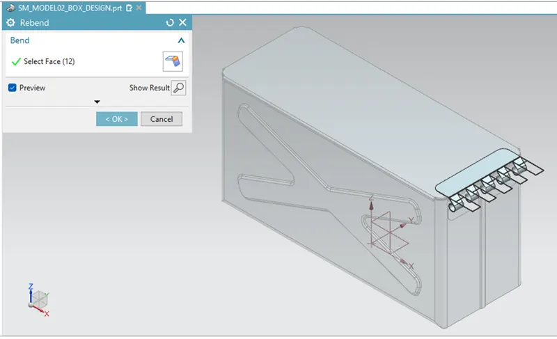
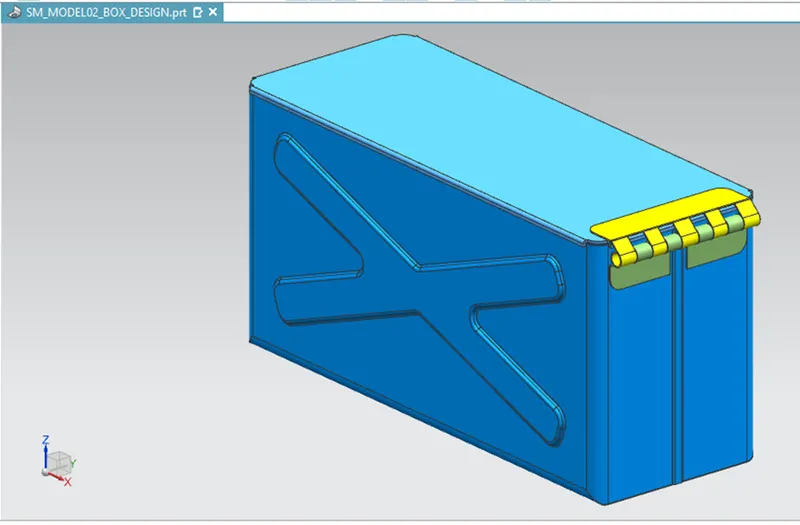
FINAL MODEL –
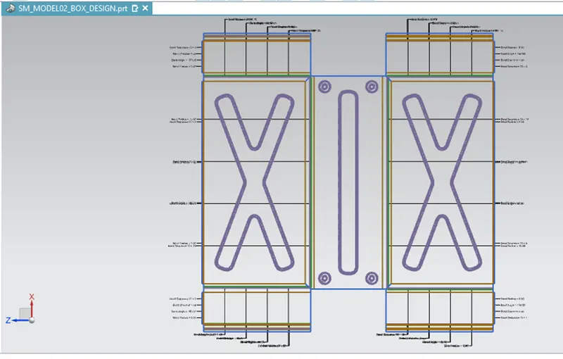
FLAT PATTERN –
BOX
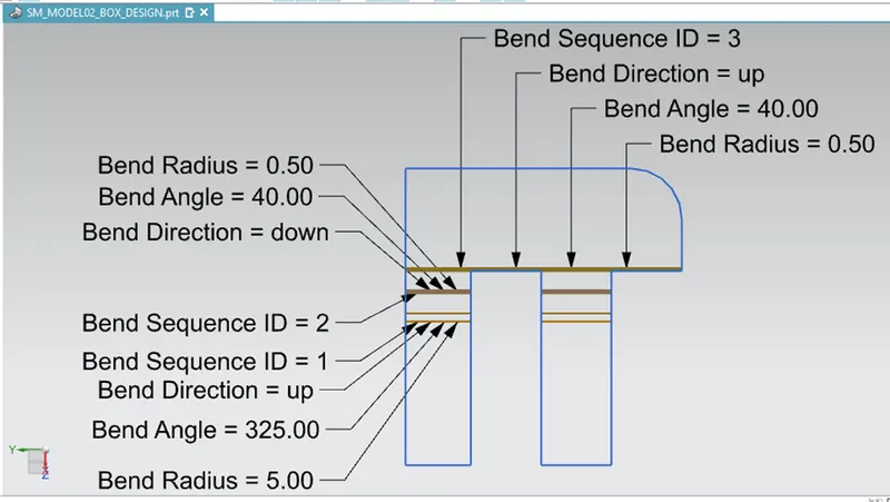
HINGE - BOX
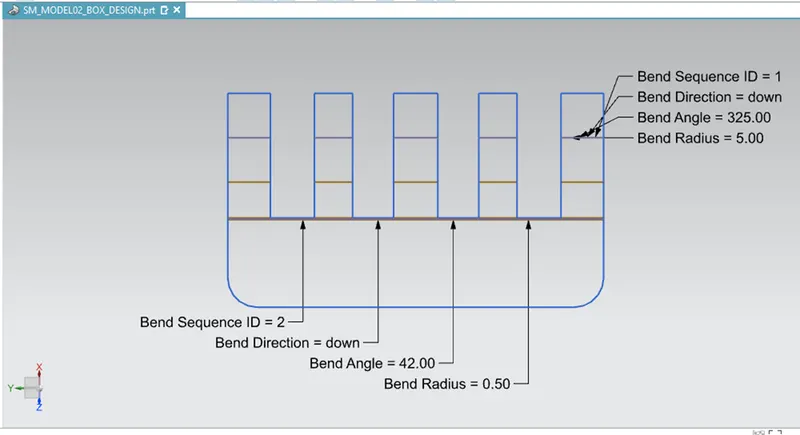
HINGE - LID
PROJECTION VIEW – FRONT
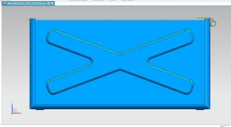
PROJECTION VIEW – RIGHT
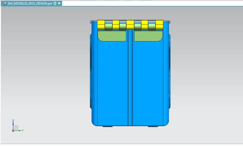
PROJECTION VIEW – ISOMETRIC
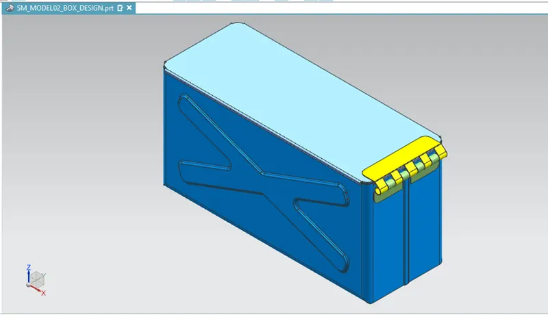
PROJECTION VIEW – TOP
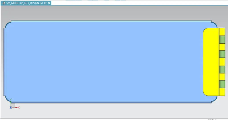
PROJECTION VIEW – BOTTOM
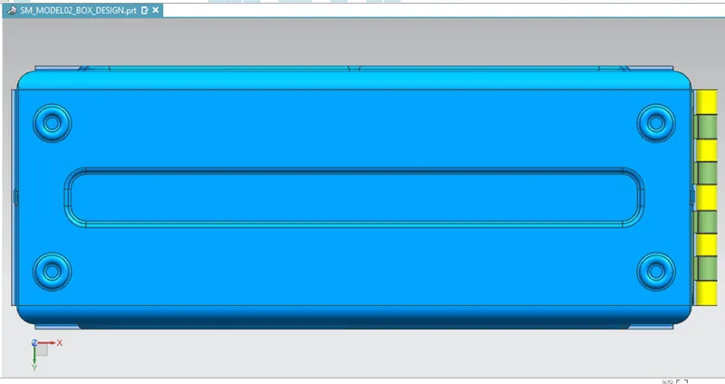
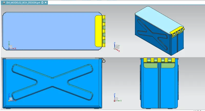
FOUR VIEW LAYOUT –
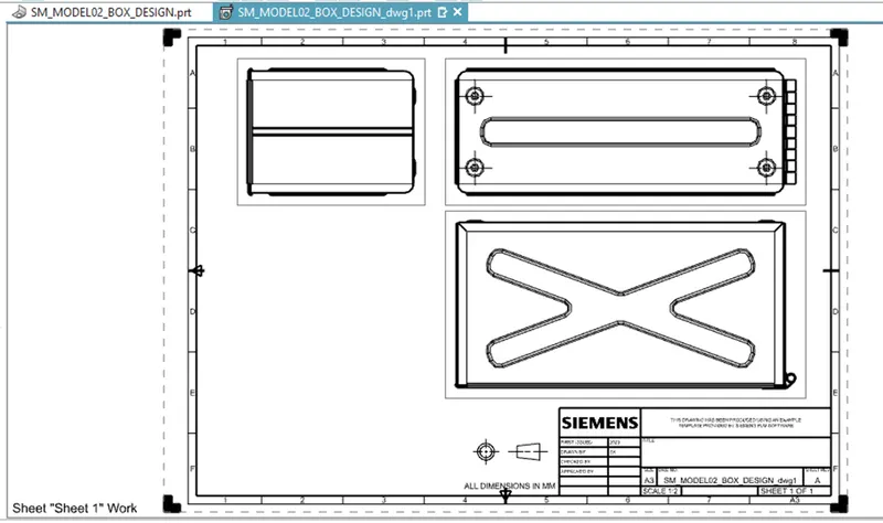
DRAWING SHEET –
=====================================