Advanced Sheet Metal Design Using NX Cad Challenge_2_Box Assembly
SHEET METAL BOX ASSEMBLY
OBJECTIVE: To make sheet metal box assembly using Siemens NX sheet metal application.
SHEET METAL: Sheet metal is metal formed by an industrial process into thin, flat pieces. Sheet metal is one of the fundamental forms used in metalworking, and it can be cut and bent into a variety of shapes. Countless everyday objects are fabricated from sheet metal.
SHEET METAL DESIGN IN CAD: Sheet metal design software considers the fabrication methods needed for manufacturing.
DESIGN METHODOLOGY:
| 1. | make tab |
| 2. | make flange |
| 3. | make closed corner |
| 4. | make hem |
| 5. |
mirror body |
| 6. |
unite |
| 7. | do unbend |
| 8. | rebend |
| 9. | make sketch and dimple |
| 10. | make beads |
| 11. | make hem flange |
| 12. | for making lid insert new datum plane |
| 13. | sketch on this plane |
| 14. | create tab |
| 15. | again create tab on side face |
| 16. | make flanges |
| 17. | make hem |
| 18. | make open loop hem |
| 19. | unbend and create sketch on the unbend face |
| 20. | do normal cutout |
| 21. | rebend the face |
| 22. | create tab on face of lid |
| 23. | create flange |
| 24. | create hem |
| 25. | unbend it |
| 26. | create sketch |
| 27. | do normal cutout |
| 28. | rebend it |
| 29. | assembly is ready |
Features used for making box assembly:
- Tab
- Normal cutout
- bend
- Flange
- Closed corner
- Hem
- Mirror body
- Unite
- Mirror feature
- Break corner
- Dimple
- Beads
- Unbend
- Rebend
- Sketch
Let us discuss the above features in detail:
- Sketch: this feature is present in modelling application. It create sketch, add curves, dimensions, constraints. Used for creating sketch for tab, normal cutout, unbend.
- Tab: creates a base feature by extruding a sketch along a vector by thickness value or add material to planar surface.
- Closed corner: this feature closes the corner where two flanges meet by extending the bends and flanges.
- Hem: this feature modifies the model by folding edge of the sheet metal flange over onto itself for the purpose of safe handling or to increase edge stiffness.
- Mirror body: it copies the body and mirrors it across the plane.
- Unite: it combines the volume of two or more solid bodies into one body.
- Normal cutout: this feature removes material by projecting a sketch onto the model and then cutting perpendicular to faces intersected by the projection.
- Bend: it modifies the model by bending material on one side of sketch adding a bend between the two sides.
- Flange: it adds flat flange at an angle to a planar face and adds bend between the two.
- Break corner: It rounds or chamfer the sharp edge of a tab or flange.
- Unbend: Flattens the bend and the material adjacent to it.
- Rebend: it restores the previous bend feature to its original position.
- Dimple: it lifts an area of the model inside the sketch that simulates a stamping tool.
- Beads: lifts material along the contour of sketch that simulates the stamping tool.
- Mirror feature: it mirrors features and sketches along plane.
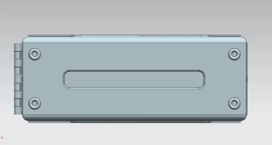
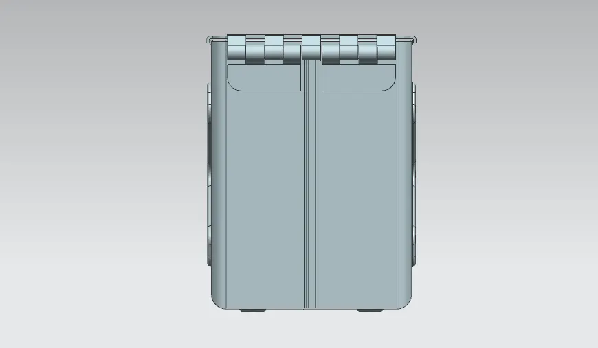
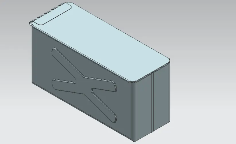
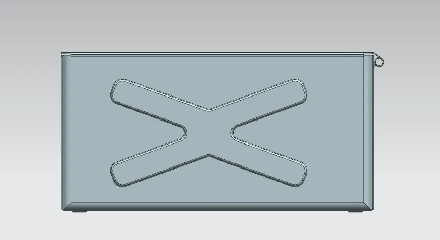
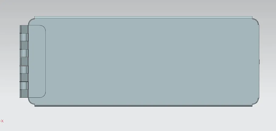
images of sheetmetal box assembly:
bottom view:
side view:
isometric view:
front view:
top view:
Conclusion:
- The design is formed in the nx 12 software and part is modelled in sheet metal application.
- Learnt some features of the sheet metal workbench while making the design.