Advanced Sheet Metal Design Using NX Cad Challenge_2_Box Assembly
BOX ASSEMBLY
Objective:
To design a box and its assembly , thus creating a draft of all components using Siemens NX Sheet metal application.
Introduction:
NX CAD includes a specialized set of tools for designing sheet metal parts and assemblies. These tools allow users to quickly create and modify sheet metal parts, including features such as bends, flanges, and other common sheet metal operations.
Some of the key features of the sheet metal design tools in NX CAD include:
-
Bend definition: Users can create and edit bend lines, bend angles, and reliefs for sheet metal parts.
-
Flange and unfold: Users can create flanges and unfold sheet metal parts to create flat patterns for manufacturing.
-
Sheet metal gauge table: Users can define and apply sheet metal gauges to parts and assemblies.
-
Punch, laser and plasma: NX CAD allows user to define the punch, laser and plasma features on sheet metal parts.
-
Sheet metal simulation: Users can simulate the behavior of sheet metal parts under different loads and conditions, including the ability to predict springback and evaluate the effects of different manufacturing processes.
-
Sheet metal nesting: Users can optimize sheet metal parts for cutting and nesting to minimize material waste.
-
Manufacturing documentation: Users can create detailed drawings and documentation for sheet metal parts, including flat patterns, bend notes, and bend tables.
Overall, NX CAD provides a comprehensive set of tools for designing and manufacturing sheet metal parts, from initial design through to final production.
Design methodology:
| New file selection in NX |

| Saved with Nx_box_assembly_GundeepSingh |
| Selected XY Plane and Sketch made with given dimensions and Tab command is performed |
| Flange command is used to create walls on the longer side on both side of rectangular base |
| Flange command is further used along the walls created |
| Hem and Flange comand is used to lock the walls of the box |
| Corners are closed using closed corner feature |
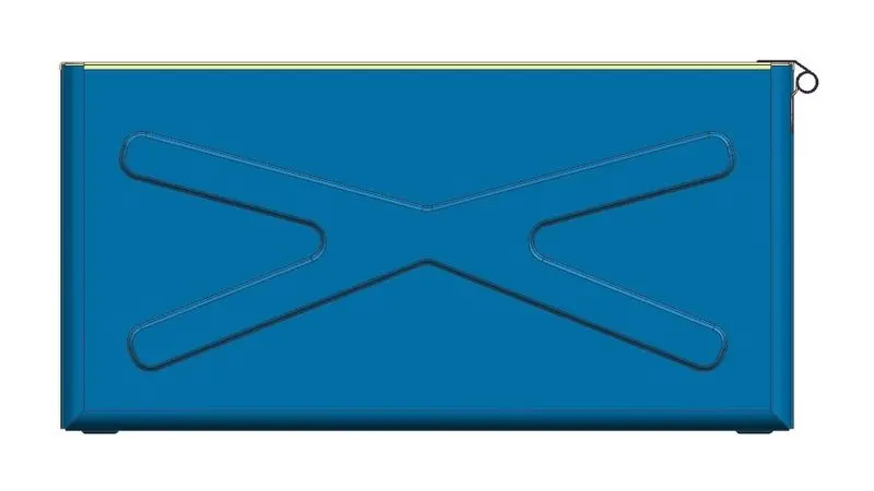
| Sketch is created on the longer wall , thus dimple command is performed |
| Mirror the profile to the other wall using mirror feature command |
| Sketch is created on the Surface of tab and performed dimple operation |
| Rectangular shape sketch formed and dimple command is performed in the sketch at the base of the wall |
| Datum CSYS is created at the free end of the tab |
| Hem flange is created on the top of the walls on each side |
| Mirror command is performed to create the box and beads are created at the bottom of the base at the corners |
| Box is unites and Lid is created using Tab command on datum plane |
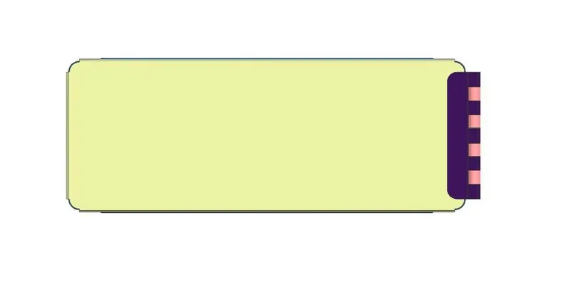
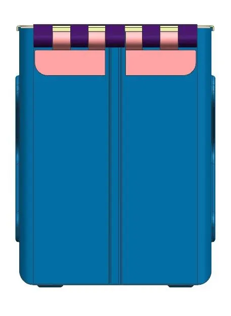
| Flanges are formed at the four sides of lid and later tab ,break corner, flange and normal cut out commands are used on the wall to create the hinge |
| Another Hinge is created by mirror command, similar hinge is created on lid |
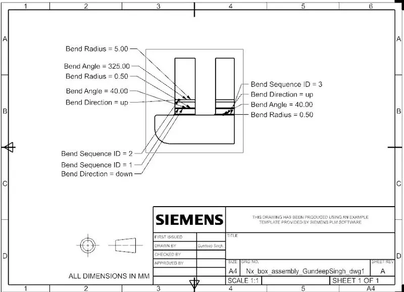
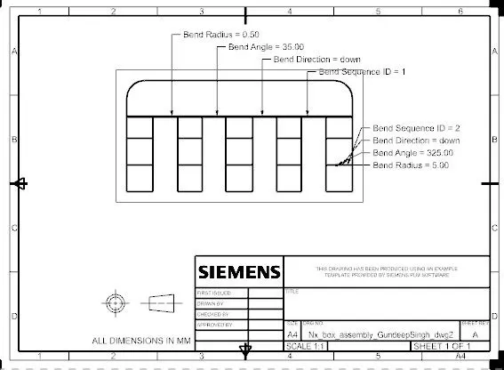
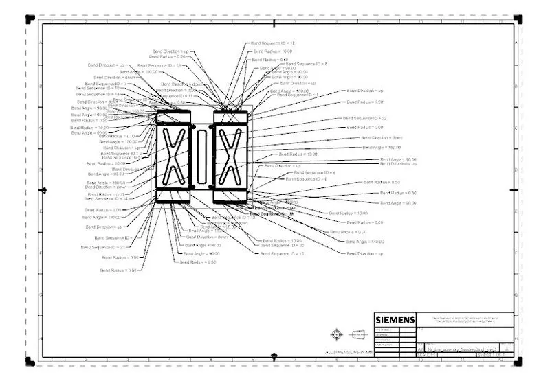
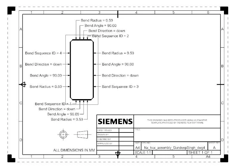
| Drafts are created for all the flat pattern and bottom hinges are formed |
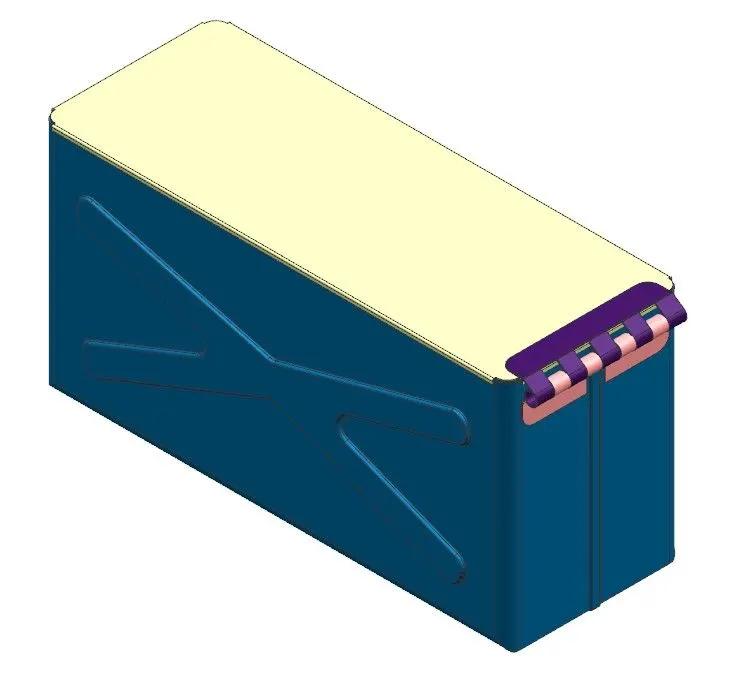
| Finally , giving differnt colors to the different part of the assembly, Hence assembly formed |
Description :
Sketch:- Allows to create and edit 2D geometry for use in 3D modeling.
Tab :- Create a tabular layout of items, such as dimensions or annotations, within a drawing.
Bend :- It is used to create a bend in a sheet metal part. It Can specify the bend angle, bend radius, and the location of the bend on the sheet metal part.
Flange :- It is used to create a flange on a sheet metal part. A flange is a projecting flat surface or rim used for strengthening or attaching to another object
UNBEND :- It is used to remove a bend from a sheet metal part.It can be used to change the shape of a bent sheet metal part back to its original flat state.
DIMPLE :- It is a shallow depression or indentation on a sheet metal surface, often used to provide clearance or to improve the appearance of a part.
BEAD :- It is a raised ridge or protrusion on a sheet metal surface, often used to provide strength or to improve the appearance of a part.
REBEND :- It can be used to make changes to a bend after it has already been created, such as to correct an error or to make design changes.
Normal cutout:- It cuts the material by projecting a sketch onto the model and then cutting perpendicular to the faces intersected by the projection.
Break corner:- It rounds or chamfers a sharp corner of a tab or flange. It is used in the tab created for hinge.
Unite:- It combines the volume of two or more bodies into a single body.
Hem flange:- It modifies the model by folding the edge of a sheet metal flange over onto itself for the purpose of safe handling or to increase edge stiffness.
Images:
Conclusion:
By performing this task, I have learned how to use commands like tab, flange, break corner, closed corner, dimple, hem flange, bead, rebend, datum plane, datum coordinate system (Datum CSYS), flat pattern, mirror feature, mirror body, unite, normal cutout and unbend by creating a box assembly.