Advanced Sheet Metal Design Using NX Cad Challenge_2_Box Assembly
TITLE OF THE PROJECT: Advanced Sheet metal design using Siemens NX cad - Box Assembly.
OBJECTIVE: To design a box assembly and create a drawing of it using the Siemens NX CAD
INTRODUCTION
Sheet metal is metal formed by an industrial process into thin, flat pieces. Sheet metal is one of the fundamental forms used in metalworking, and it can be cut and bent into a variety of shapes. Countless everyday objects are fabricated from sheet metal. Thicknesses can vary significantly; extremely thin sheets are considered foil or leaf, and pieces thicker than 6 mm (0.25 in) are considered plate steel or "Structural Steel".
Sheet metal is available in flat pieces or coiled strips. The coils are formed by running a continuous sheet of metal through a roll sitter.
NX Sheet Metal: Creating fast, accurate flat patterns is the goal of any organization that manufactures products that contain sheet metal parts. NX Sheet Metal provides a set of tools within the NX design environment that allows for simple and fast design of sheet metal parts, dependent on their material and manufacturing process, the most common of which is straight brake sheet metal forming.
With NX Sheet Metal, formed and unformed representations of the parts are created closely following the industry workflows and best practices for bending calculations, tooling, and sheet metal features. The value lies in improving quality and reducing the cost of sheet metal parts by producing an accurate sheet metal pattern as the correct input for part manufacture, whether internally or to a supplier.
DESIGN METHODOLOGY
The design methodology is explained by the flow chart as follows;
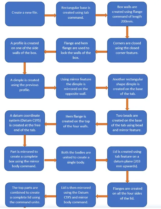
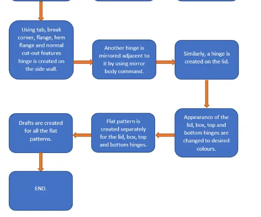
Description:
Features Used in making the Box:
Sketch: It is a basic command to draw 2d models
Tab: This command is used to create a base feature by extruding a sketch along a vector by a thickness value or by adding material to existing faces and bend regions of the sheet metal parts.
Flange: This command is used to add a flat flange at an angle to the planar face and add a bend between the two. A flange consists of a bend region and a web.
Closed Corner: This command is used to modify two flanges in one operation and to close the corner where the two flanges meet.
Hem Flange: This command is used to modify an edge of a sheet metal part by folding it onto itself for the purpose of safe handling or to increase edge stiffness.
Mirror Body: This command is used to mirror the part w.r.t the required axis.
Unite: This command is used to combine the two parts into one part.
Dimple: This command is used to lift an area of the model inside the sketch that stimulates a stamping tool.
Mirror Feature: This command is used to mirror the required sketch to another side with reference to the axis.
Unbend: This command is used to flatten the 3D model by selecting one stationary face.
Rebend: This command is used to rebend the flattened sheet material.
Bead: This command is used to lift material along the contour of a sketch that stimulates a stamping tool. Bead can also be created to stiffen the material.
Datum Plane: This feature is used to project the plane at a certain distance by giving the distance.
Normal Cutout: This command is used to remove the unwanted material w.r.t to the sketch.
Break Corner: This command is used to round or chamfer sharp corners of a tab or flange.
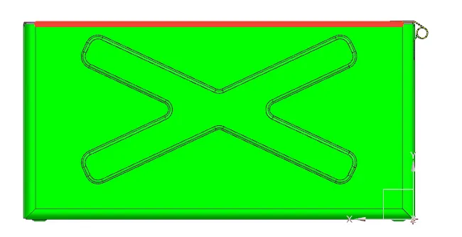
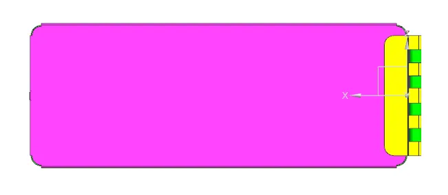
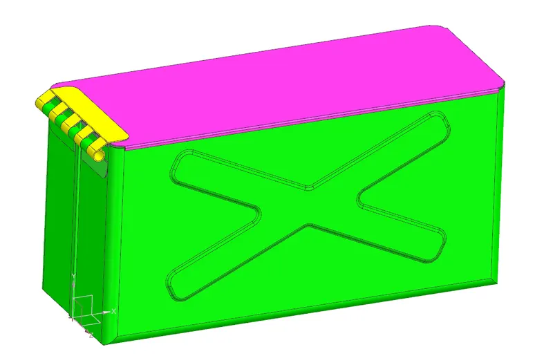
Images of a Box Assembly:
Front View
Top View
Side View
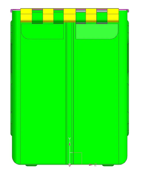
Isometric View
Conclusion
By performing this task, I have learned how to use features like tab, flange, break corner, closed corner, dimple, hem flange, bead, rebend, datum plane, datum coordinate system (Datum CSYS), flat pattern, mirror feature, mirror body, unite, normal cutout and unbend by creating a box assembly.