Advanced Sheet Metal Design Using NX Cad Challenge_2_Box Assembly
BOX ASSEMBLY DESIGN USING NX CAD
OBJECTIVE:
To design a Box Assembly using the NX CAD tool.
INTRODUCTION:
The learning of steps & features involved in designing a Box Assembly using an NX CAD tool.
DESIGN METHODOLOGY:
DESCRIPTION:
BOX:
STEP 1:
Start NX CAD. Then set the global parameters as per requirements.
Menu-->Preferences-->Sheet metal
STEP 2:
Design a base sketch for the box and create a base with a Tab option
TAB: A tab is used to form a base of the model along the planar face with respective thicknesses. A sketch with single or multiple closed profiles can be formed as a base
STEP 3:
Use the Flange option to form the side bodies of the box.
FLANGE: The flange feature creates a flat bent profile at an angle to a planar face.
STEP 4:
Then apply a closed corner at the adjacent bends for both sides.
CORNER: The corner feature helps to close a corner where two adjacent bends meet.
STEP 5:
After closing the corner, use Hem Flange to create a ‘U’ profile which self-locks the sheet metal after bending.
HEM FLANGE: Hem Flange is used to modify the model by folding the edge of the sheet metal flange over onto itself.
STEP 6:
Now mirror the body to form a replicate of the existing body.
MIRROR: Mirror feature mirrors the selected face or body across the selected planes or lines.
STEP 7:
Now unite the two bodies (Existing body & Mirrored Body).
UNITE: Unite features used to unite the selected bodies into a single body.
STEP 8:
Now create a sketch and make a dimple on the front & bottom side of the box and mirror it on the backside.
DIMPLE: Dimple is one of the punching processes which is used to raise an area of the model perpendicular to the face where the contour sketch is drawn.
STEP 9:
After that, create a sketch for creating beads. Then select the bead option with a circular cross-section and give proper radius and depth and mirror it to make it four beads at the bottom.
BEADS: Beads are used to lift a material along the contour of the sketch.
STEP 10:
Then use a hem flange at the top edges to create a ‘U’ shaped corners which neglects the sharp edges and create a smooth & safer edge.
HEM FLANGE: Hem Flange is used to modify the model by folding the edge of the sheet metal flange over onto itself.
LID:
STEP 11:
Create a datum plane at resp distance. Then design a base sketch for the lid and create a base with the Tab option.
STEP 12:
Use Flange to create the bends in the lid which seats on the sides of the box.
(3) HINGE:
STEP 13:
Using the right side face of the box as a reference, create a base for the hinge using a Tab option.
STEP 14:
Use the break corner option on the hinge base to avoid the sharp edge.
STEP 15:
Then using the flange and hem flange, create a circular profile with the dia where the hinge rod gets inserted to lock.
STEP 16:
After creating the flange, unbend the profile with the use of the Unbend option.
UNBEND: This feature is simply used to flatten the bent profile.
STEP 17:
Create a sketch that has to be cut out from the profile with Normal Cutout.
NORMAL CUTOUT: A cutout profile is used to remove the material from the base.
STEP 18:
Then rebend the model & mirror it to get the best view of the model with the replication of the existing body.
REBEND: Rebend is used to restore the model to its bent state.
STEP 19:
Repeat the same steps for mating the hinge by taking the top side of the lid as a reference for creating a tab.
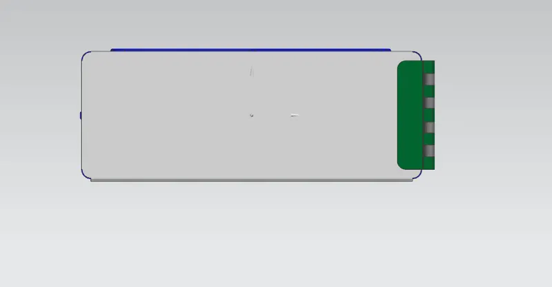
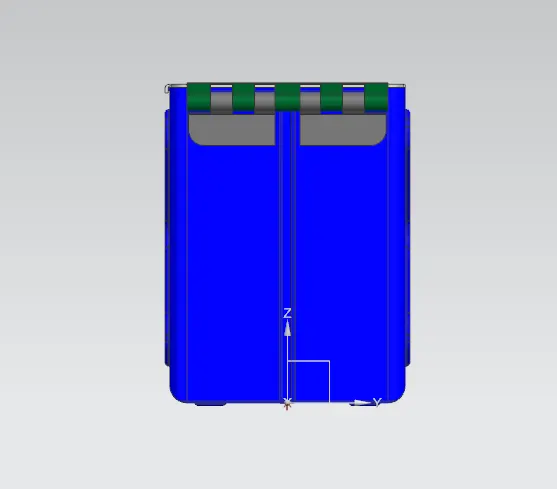
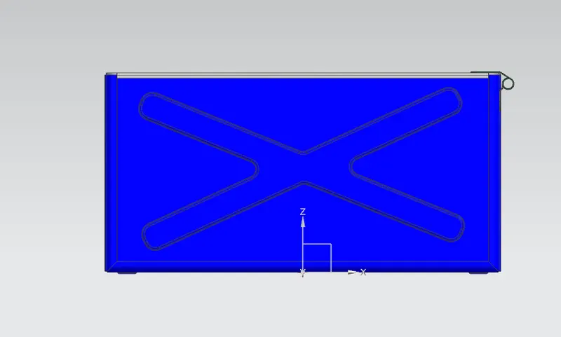
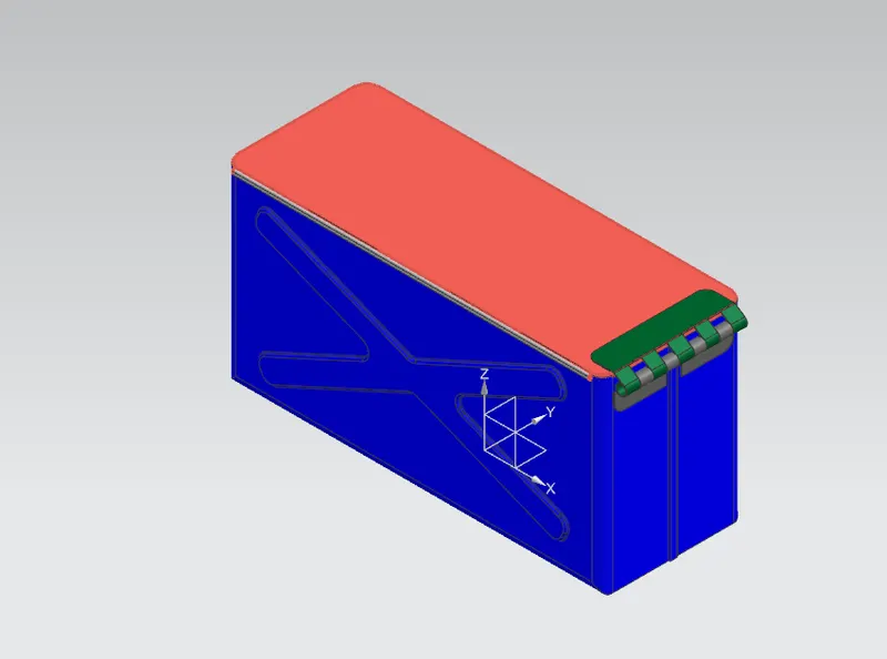
HERE ARE SOME OF THE SCREENSHOTS OF THE MODEL:
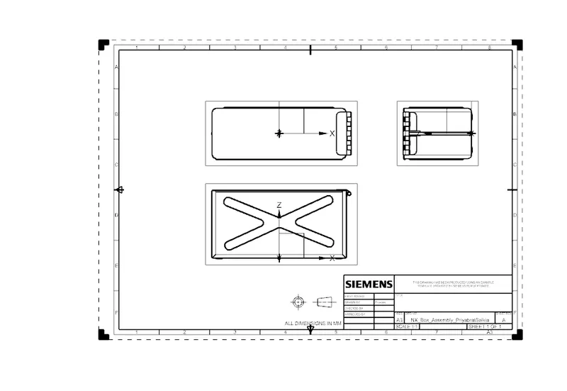
Drawing Sheet:
CONCLUSION:
Thus the Box Assembly has been designed with the use of the NX CAD tool and learned about the features involved in creating the sheet metal model.