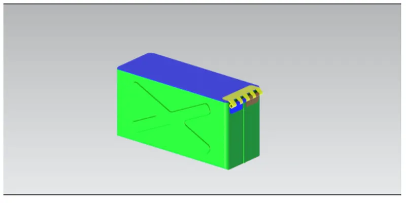
Advanced Sheet Metal Design Using NX Cad Challenge_2_Box Assembly
Design of Sheet metal Box Assembly using NX-Cad
Objective
The main objective of this project is to design a sheet metal Box assembly by understanding different operations in Siemens NX-cad. Then Drawing sheet is to be created for the designed sheet metal Box.
Introduction
Sheet metal is metal formed by an industrial process into thin,flat pieces. Sheet metal is one of the fundamental forms used in metal working,and it can be cut and bent into a variety of shapes. Countless everyday objects are fabricated from sheet metal. Sheet metal is available in flat pieces or coiled strips. The coils are formed by running a continuous sheet of metal through a roll slitter. Parts manufactured from sheet metal must maintain a uniform thickness for ideal results. There are many different metals that can be made into sheet metal,such as aluminum,brass and steel.
In this project box Assembly was created to understand the basics of sheet metal application in Siemens NX. These Box Assembly has some important features like flange, dimple and normal cutouts. It is an basic component which can be used as CPU cover and other electronic components.
NX, formerly known as "Unigraphics", is an advanced high-end CAD/CAM/CAE,which has been owned since 2007 by Siemens PLM Software. In 2000,Unigraphics purchased SDRC I DEAS and began an effort to integrate aspects of both software packages into a single product which became Unigraphics NX or NX.
Design Methodology
Design Requirements
Sheet Parameter = 200mm* l50mm*lmm
List of Features used for designing the Casing:
Sketch - It is a basic and initial operation for creating any kind of sheet metal components.
Tab - It is a base feature that forms by extruding the sketch along a vector by providing thickness or adds material to a plane face.
Normal cutout - It cuts the model perpendicular to the sketch.
Bend - It modif ies the model by bending the material on one side of a sketch line by adding a bend between two sides.
Flange - It adds a f lat f lange on basis of edges at an angle to a planar face and adds bend between them.
Hem Flange - It modifies the model by folding the edge of a sheet metal f lange over onto itself for the purpose of safe handling or to increase edge stiffness.
Break corner - It Rounds a sharp corner at edges
Unbend - It f lattens a bend and material adj acent to the bend.
Mirror - It is used to create same features or sketches on basis of plane or sketch.
Hole - It creates a whole on basis of circle created.
Dimple - It lifts an area along the contour of a sketch that forms an stamping tool. Bead - It lif ts a material along the contour of a sketch that forms an stamping tool. Rebend - It restores a bend
Unite - Combine the volume of two or more solid bodies into a single body.
Flat pattern - It creates a f lattened pattern from the formed sheet metal part. Procedure for designing Box Assembly
Procedure for designing Box Assembly
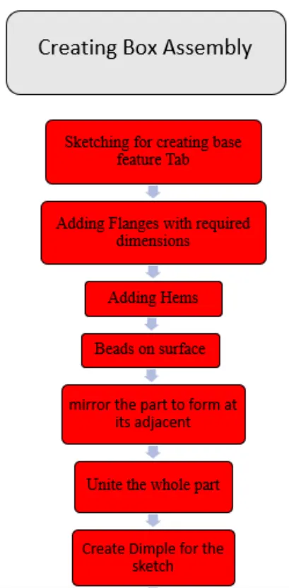
- At first sketch is drawn by using rectangle for creating Then flanges are added to edges that are parallel to each other.
- Another flange to these f langes is added on both si Closed contours are added to two flange edges.
- Flanges are added to edges of each f langes. Then Hem is added to these f lange edges on both sides that looks like insert on another hem.
- Then whole part is selected to form on adjacent side by selecting proper plane as reference.
- Whole body is selected to apply unite that forms as single body.
- One of the faces is selected to sketch with proper geometry for applying dimple with required
- By using mirror feature these dimples is selected to form on other face of body.
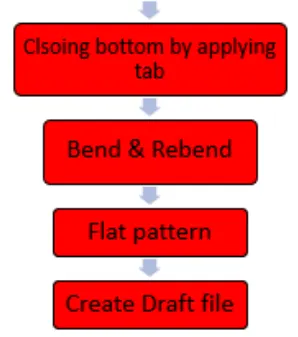
- Then unbend the total body and rebend to original position. Bead is added on surface of
- Above bead is selected for applying mirror Feature on basis of required plane for creating more beads.
- New datum plane is created for sketching bottom surface of box for making as closed Required flanges are added to close the part.
- Rectangle is drawn on surface for creating Break corners are added to required edges.
- Another flange is added to these tabs with required dimensi Hem f lange with circular profiles are added to these f langes.
- Then unbend the tabs and f lat pattern is applied to whole
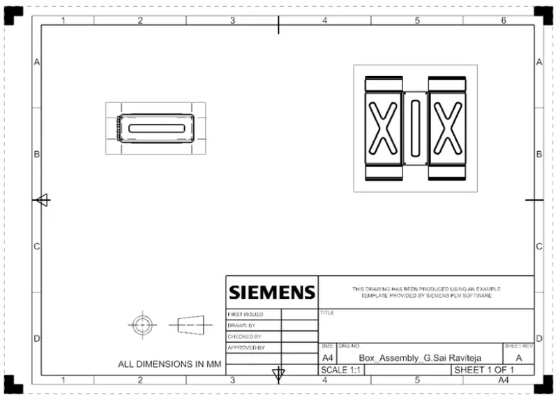
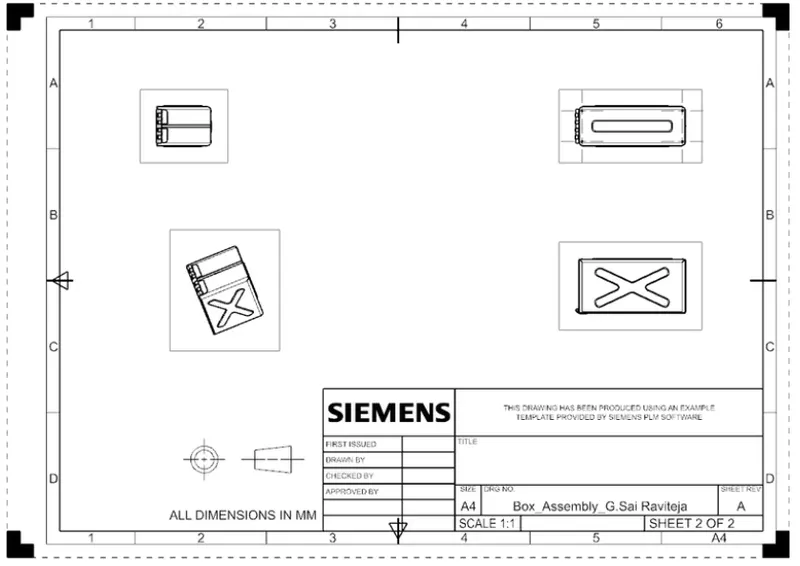
- Required colors are added to all parts in a assembly. New draft file is created for drawing these parts with required dimensions.
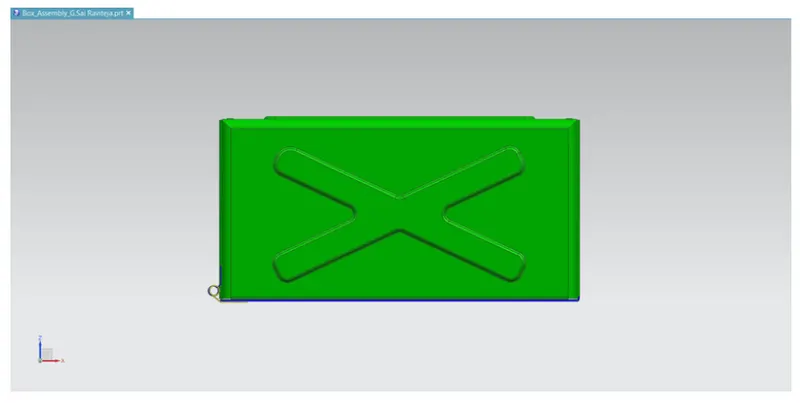
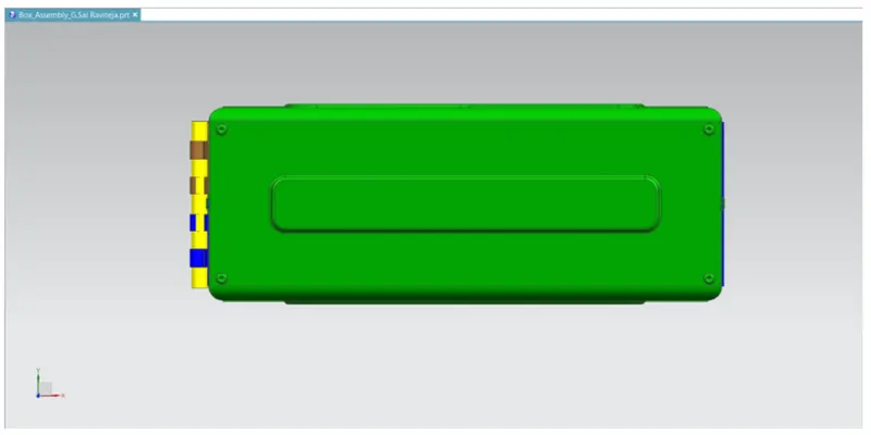
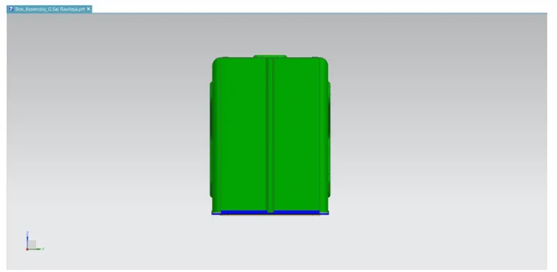
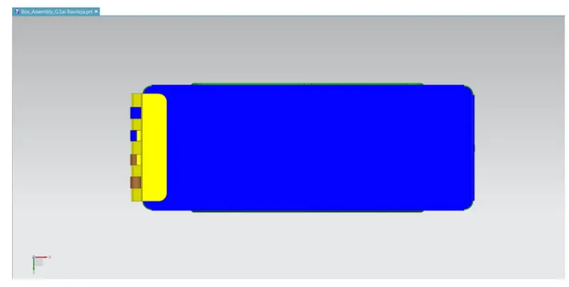
Different views of Casing
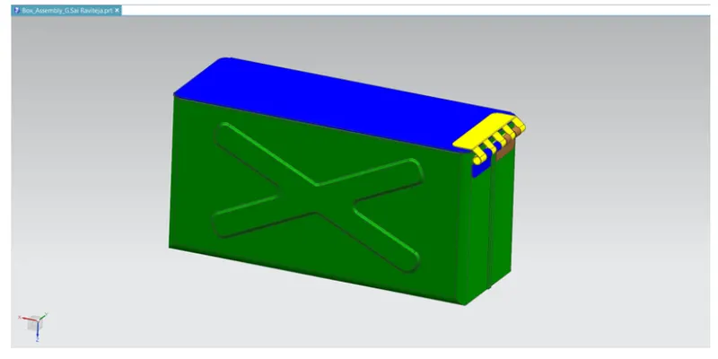
Isometric view:
Front view:
Top view:
Right view:
Bottom view:
Drawing sheet of casing:
Conclusion:
Thus the designing of box assembly by using Nx-CAD applications has been craeted and drafted