Advanced Sheet Metal Design Using NX Cad Challenge_2_Box Assembly
BOX ASSEMBLY
make a sketch on bottom plane at the rectangle of 200m and 150mm dimensions
create a base sheet by using tab commant at 1mm thickness
make sheets at 2 sides of base sheet at 200mm lenth and 10mm raidus of cuvature
make another flange in the 150mm side at 70mm length for two sides 200mm flange
joining the corners by using closed corners command at two ends
make the smaller flange at at the end of 70mm sheet , at the length is 0.001999 and 0mm bend radius
then creat another flanges at 6.5mm length and 0.5mm bend radius , flange is is bended in to outside
create a hem flange in the open condition , at the 0.503mm radius and 5mm length for two sides
make the hem flange for accurate to adjust the bend radius
mirror all the body at the y-z is the refference plane
combine all the sheet by using unite command
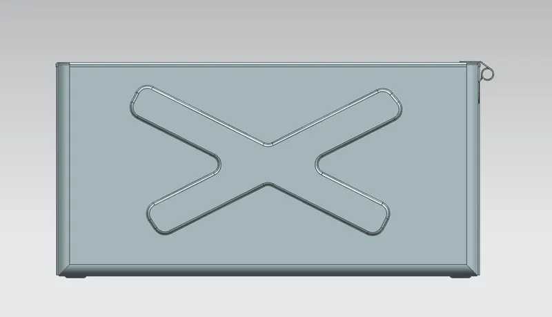
create a sketch 16 on the side sheet at 10mm radius
dimple apply on the sketch 16 at 2mm depth and outside direction
then mirror the dimple on the opposite surface by using mirror feature command
create another sketch (20) on the base sauface
then dimple apply on the sketch 20 in inside direction
apply the unbend and rebend command on the sheets
make bead on the corner of base plane at circular cross section and depth and radius is 2mm
mirror the bead on the remaing corners by using mirror feature
create hem flange on the opne faces of sheet metal in the closed type and 2mm lenth
create a datum plane from the bottom surface upto 203mm length
make a sketch oon the new plane as given dimension
make surface into bottom by using tab at 1mm thickness
then apply on the flange in the top sheet as refference of hem flage at 3mm length
create a sketch on the flanges side at rectangel of 20and 55mm dimension
apply tab command to create 1mm thickness sheet and remove the bottom side corner at 10mm radius
make flange on the end of now maked sheet at 4mm length and 40deg angle
similarly make another flange on the end of flange sheet
create a hem flange on the above maked flange at 5mm length and 325 deg angle
unbend the flanges and make sketches on surface as given dimension
cut the flanges at the refference of sketch 46 , then unbend the flanges
mirror the flange creation into opposite side using mirror geometry
create sketch on the top sheet at the side of flanges creation, then make a sheet at 1m thickness
remove the edges of now makes sheet at 100m radius by using break corner command
make flanges on on the outer edges of top sheet at 13mm length and 39ddeg angle
then apply hem flange at 5mm radius and 325deg angle
unbend the flanges and make sketches as refference
cut the extraa portions by using sketch 56
then rebend the flanges
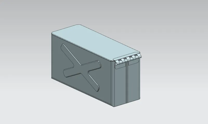
save the part file as BOX ASSEMBLY
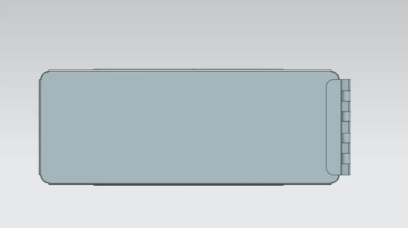
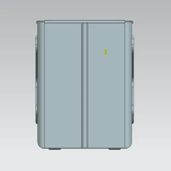
part views:
Conclusion:
l learned various tools for sheetmetal design