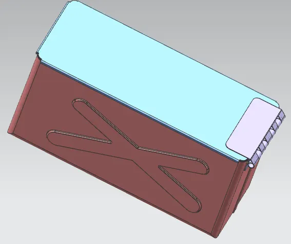
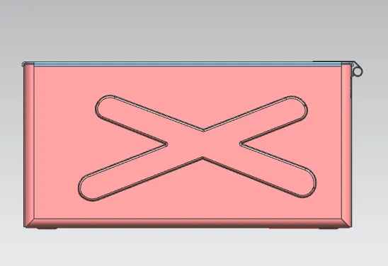
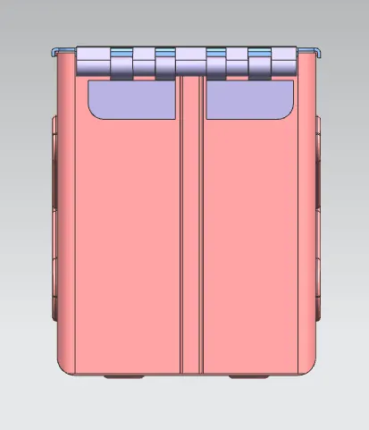
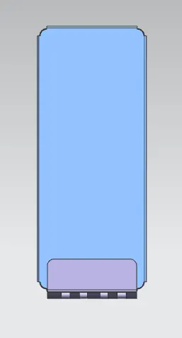
Advanced Sheet Metal Design Using NX Cad Challenge_2_Box Assembly
BOX ASSEMBLY DESIGN USING NX CAD
Objective:
to design a box assembly using nx cad
INTRODUCTION
Sheet metal is metal formed by an industrial process into thin, flat pieces. Sheet metal is one of the fundamental forms used in metalworking, and it can be cut and bent into a variety of shapes. Countless everyday objects are fabricated from sheet metal.Sheet metal is available in flat pieces or coiled strips. The coils are formed by running a continuous sheet of metal through a roll slitter Parts manufactured from sheet metal must maintain a uniform thickness for ideal results
ddESIGN METHODOLOGY
THis is the approach that show in the part navigation which command did we do first and then whichone
use tab to create the base of the box
↓
use flanges to create the side bends
↓
use corners to close the two adjacent bends
↓
use hemming to create u shaped profile
↓
use mirror to replace the existing body and unite it
↓
create dimple and Beads
↓
create smooth corners with break corners
↓
create a lid with tab , flange adn then by hemming
↓
create a hinge base
↓
use flange and hem to form the hinge part
↓
use normal cut out to cutr the profile in required shape
↓
repeat for the mating hinge
↓
save the profile as NX_BOX_ASSEMBLY_BIBIN.C
PROCEDURE
the procedure for the box assemply is given below
(1) BOX
(a) TAB
create a base sketch for creating the box and use tab to create the base
TAB :Tab is used to form the base of the modelling with respective thickness . A sketch with single r multiple closed surface can be formed as tab
(B)Flanges :
use flange option to create the side wall of the boxes
flange is used to create the flate bend profile at an angle to the planer face
(c) CORNERS
apply the closed corners at the end of the both adjusent sides
CORNERS:it is use to close the corner where two adjusent bend meets
(D) hemming flange
after closing the corners use hemming flange to close the sheet metal after bending
Hemming : hemming flange is used to fold the edges of the sheet metal fanges over on itself
(E) MIRROR
now mirror the body to creat the replicant of the existing body
Mirror : mirror is used to mirror the selected body or face across the selected plane
(F) Unite
now unite the mirrored body and the existing body
UNITE : it is used to combine different part bodies to single part body
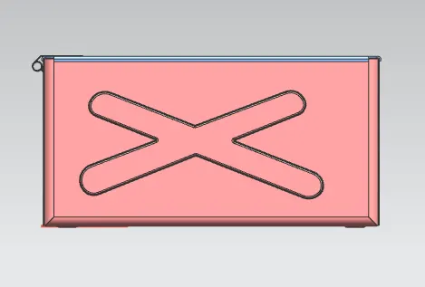
(G) Dimple
now creat the sketch to creat the dimple and creat it on the front side and mirror it on the back side of the box
DIMPLE : dimple is one of the punching process which is smilar to the emboss which provide stength to the part
(H) BEADS
after dimple draw a sketch to create the beads after creating the bead mirror it on the corners of the box
BEADS : bead is also similar to dimple but it is used to lift the material along the contour of the sketch
(I) HEMMING
again hemming falnge is used to creat a u shaped flange on the edges inorder to get smooth and safty corners
2 : LID :
(A) datum plane
create a datum plane on respective distance and create a base sketch and use tab option to creat the base
(B) break corners
use break corners to avoide the sharp edges
3 : HINGE
(A) use a side face of a box as a reference and draw the sketch and use tab to create the base of the hinge
(B) use break corner option to blend the edges of the hinge axis
(C) then use the flange and the hemming flange create a circular profile of dia where the hinge rod inserted to the lock
(D) after creating the flange make the profile to un bend
(E) after that cut the profile for required length by using normal cut out
(F) and then rebend the model and mirror it
now repeat the same process for the mating hinge by taking top side of the lid as a reference for creating the tab