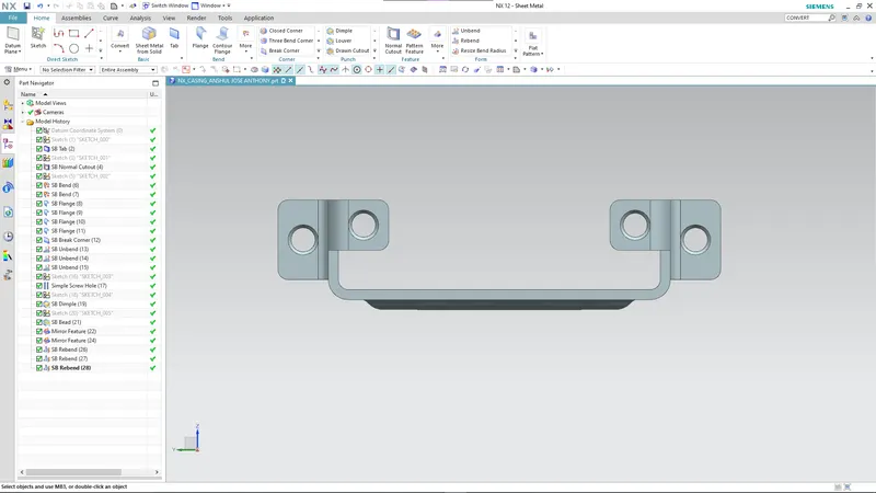
Advanced Sheet Metal Design Using NX Cad Challenge_1_Casing Design
Title of Project: Sheet Metal Casing design using NX CAD
Objective: Following design methodology based on industrial practices to cerate a casing in NX CAD
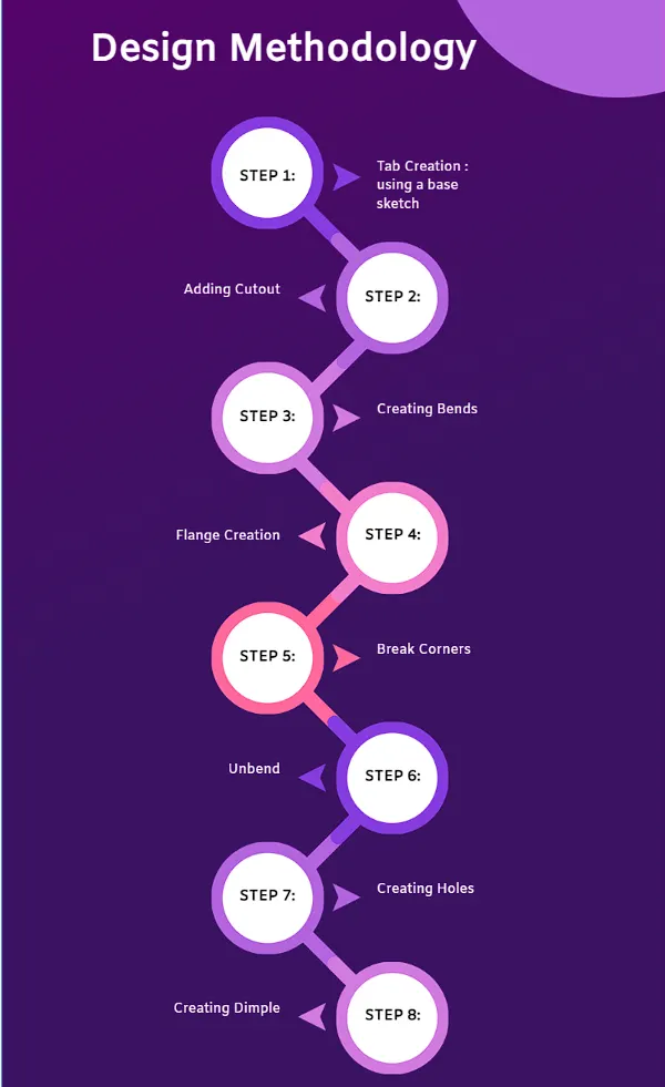
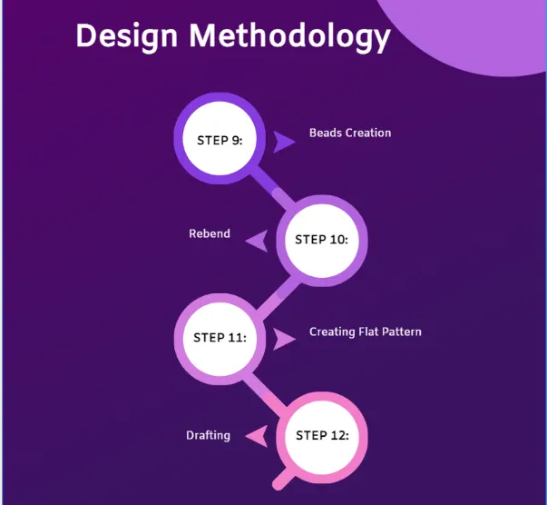
Features/Commands Used:
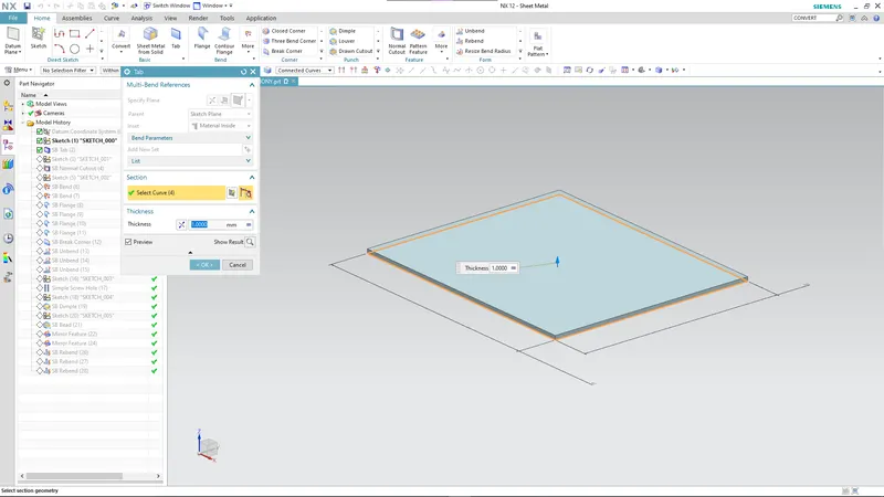
Sketch: The sketch tool is used as the name implies for creating a 2D sketch. This requires a plane as a support. The sketch for the base tab is crated in the XY-plane to create a 50x60 rectangle.
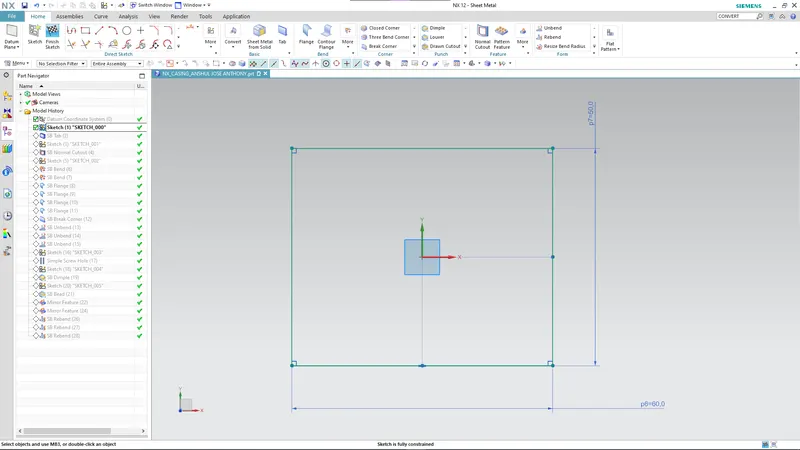
Tab:
Used to create a sheet metal plate from a correspondent sketch. It is the first parent feature in tthe sheet metal workbench. The other features such as cutouts, flanges, bends, etc., are derived form this feature. The thickness is defined to be 1 mm form all the global settings in Menu>Preferences>Sheet Metal
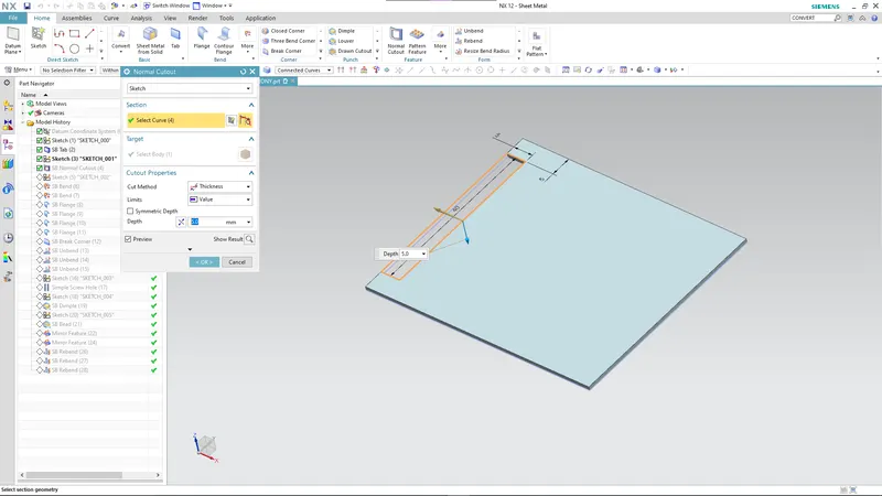
Normal Cutout: This feature is used to create cutout in the base tab based on the sketch made in the supporting plane which must lie on any of the primary tab faces. The cutout is created for a sketch of 5x40 mm adjacent to one of the edges
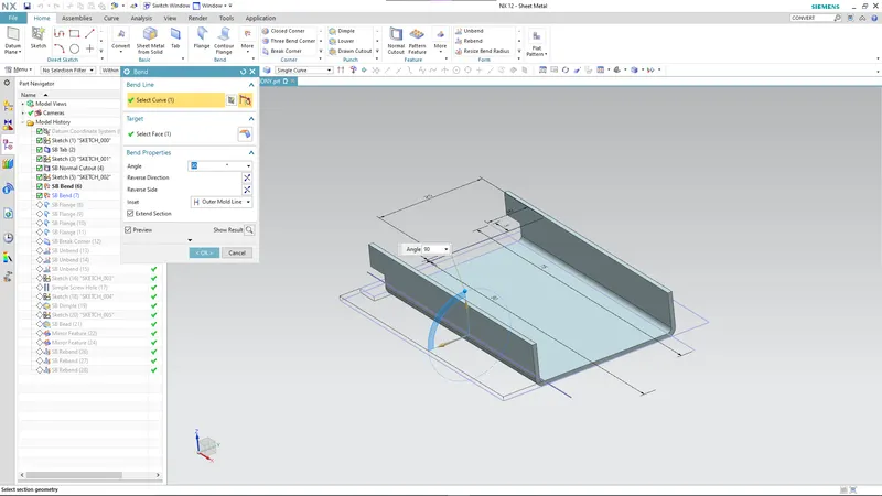
Bend: This feature is used to bend the sheet metal at defined locations. Here, these locations are two lines symmetric about the x-axis.
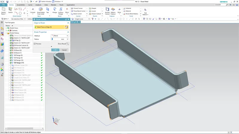
Flange: Used to add extra material at the edges of the sheet metal component. The orientation and the size of the can be controlled.

Break Corners: The "Break corner" feature is a valuable tool used in sheet metal design to enhance the overall structural integrity of the part. By applying this feature, designers can effectively smoothen or chamfer the sharp edges of the sheet metal part. This helps in reduction of stress concentration.
Unbend: This command is used to unbend the sheet metal at the bend locations to get a flat surface. This makes it easier to add features such as beads, dimples before rebending the component. The order if unbending should be sorted out as this imlicates the order of rebending.
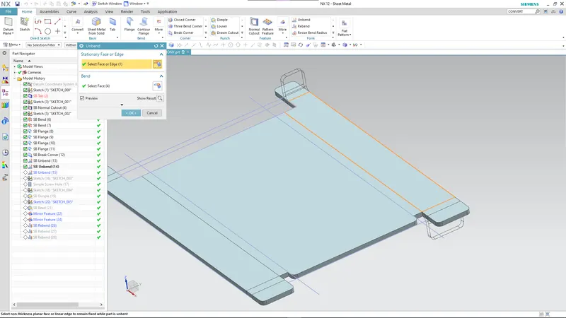
Mirror Curve: Used to mirror a curve in the sketch workbench about a defined centerline.
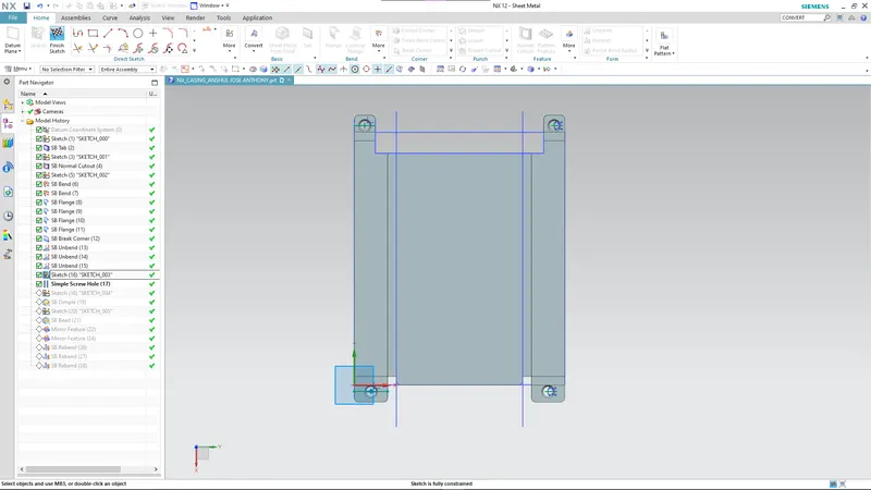
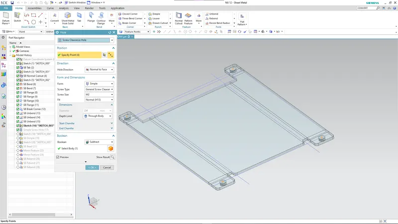
Hole: This feature is used for creation of standard or user defined holes at points contained within the component material.
Dimple: This feature is used to create a dimple using user defined sketch. A "Dimple" is a valuable feature used in modeling to raise specific areas within a sketch, simulating the effect of a stamping tool. Its primary purpose is to reinforce the flat structure and enhance the overall robustness of the design.
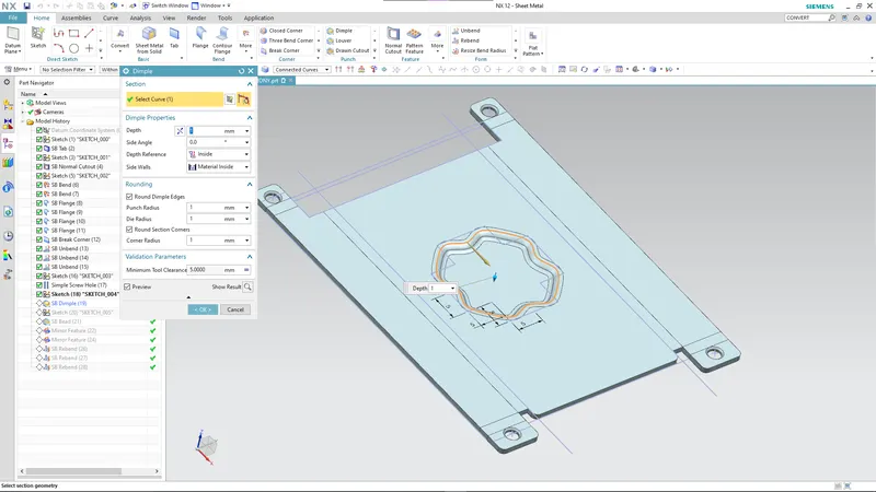
Bead: Bead is similar to dimple, but it raises the contour of the sketch instead of a specific area.
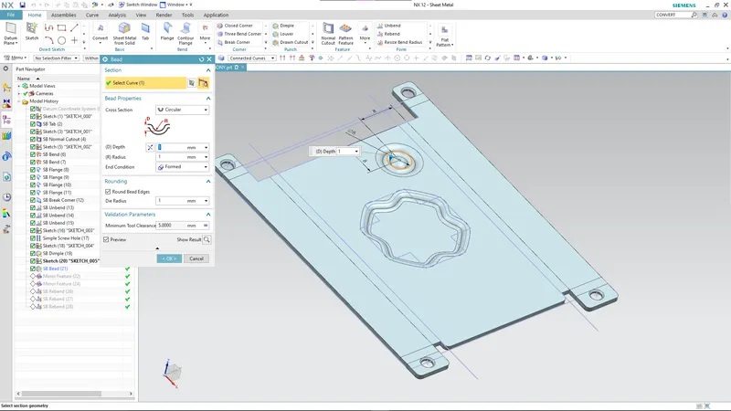
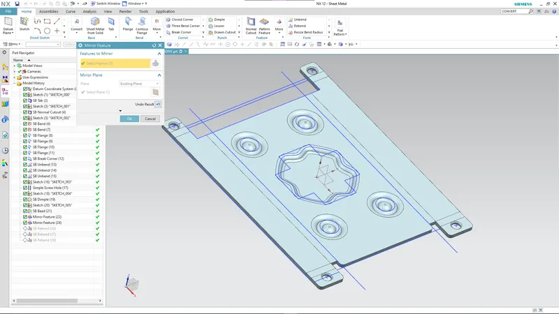
Mirror Feature: The mirror feature is used to reduce the redundancy of creating a feature withing a componenet over and over again given that the features has an element of symmetry to be leveraged.
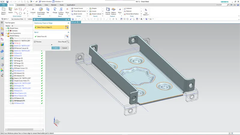
Rebend: This feature is used in conjuction with unbend so that after applying the various additions to the unbend sheet metal component, the design can be restructured to the final usable form. The order to be followed in the inverse of the order for unbend.
Flat Pattern:
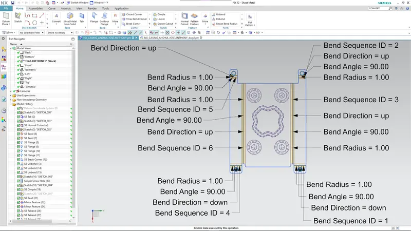
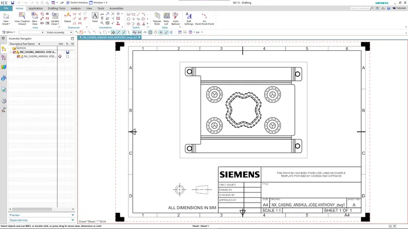
Drafting: This workbench is used to detail the component designed in the modeling workbench. This is the most important piece of data that any engineering company can possess as the final making of the product alongside it's manufacturing techniques is mentioned in the draft of the component.
Standard Views:
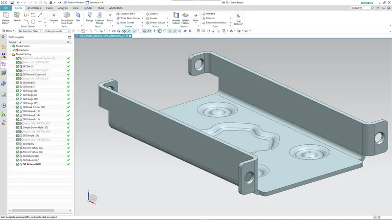
isometric
front

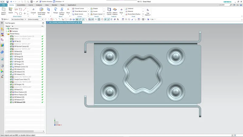
top
side