Advanced Sheet Metal Design Using NX Cad Challenge_1_Casing Design
OBJECTIVE:
The aim of this project to design a casing and create a detailed drawing for manufacture using Siemens NX sheet metal Application
INTRODUCTION:
Sheet Metal Fabrication is the process of forming parts from a metal sheet by punching, cutting, stamping, and bending.
3D CAD files are converted into machine code(CNC), which controls a machine to precisely cut and form the sheets into the final part.
Sheet metal parts are known for their durability, which makes them great for end use applications (e.g. chassis). Parts used for low volume prototypes, and high volume production runs are most cost-effective due to large initial setup and material costs.
Because parts are formed from a single sheet of metal, designs must maintain a uniform thickness. Hence the designer must be sure to follow the design requirements and tolerances to ensure parts fall closer to design intent and cutting sheets of metal.
Critical Dimensions
The following are some terminology that are used in sheet metal. Designers need to adhere to machinery guidelines when designing for bending. Bends can be defined by these parameters. Some critical dimensions that need to be considered when setting up sheet metal design in CAD software are sheet metal thickness, the k-factor and bend radius. One needs to check that these factors are consistent with the tooling that will be used in manufacturing.
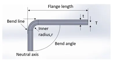
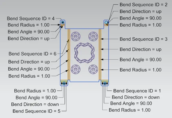
Bend line– The straight line on the surface of the sheet, on either side of the bend, that defines the end of the level flange/web and the start of the bend.
Bend radius – The distance from the bend axis to the inside surface of the material, between the bend lines.
Bend angle – The angle of the bend, measured between the bent flange and its original position, or as the included angle between perpendicular lines drawn from the bend lines.Sometimes specified as the inside bend radius. The outside bend radius is equal to the inside bend radius plus the sheet thickness.
Neutral axis – The location in the sheet that is neither stretched nor compressed, and therefore remains at a constant length.
K-factor – The location of the neutral axis in the material, calculated as the ratio of the distance of the neutral axis T, to the material thickness t. The K-factor is dependent upon several factors (material, bending operation, bend angle, etc.) and is greater than 0.25, but cannot exceed 0.50. K factor = T/t
Bend allowance – The length of the neutral axis between the bend lines or the arc length of the bend. The bend allowance added to the flange lengths is equal to the total flat length.
Software Used
NX, formerly known as "unigraphics", is an advanced high-end CAD/CAM/CAE, which has been owned since 2007 by Siemens PLM Software. In this software the sheet metal application is used to design the flat pattern required.
DESIGN METHODOLOGY:
Workflow To Design A Sheet Metal Part

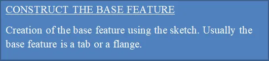
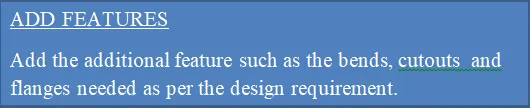
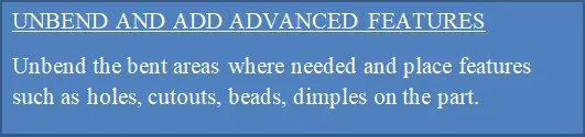
Steps For Designing The Casing





DESIGN FEATURES:
The following features are used in the project. This project was designed in the sheet metal module of the Siemens NX CAD.
- SKETCH-This command is used the draw the shape of the design.
- TAB- This command is used to create the base feature of the sheet metal. In this project a rectangular tab is created of dimensions 60mm x 50mm.
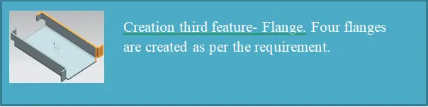
- FLANGE-This command is used to create the bend part attached to the side of the base feature. Four flanges are created in this project.A flange of 5mm length is created.
- NORMAL CUTOUT- This command is used to create a cutout by projecting a sketch onto the model and then cutting perpendicular to the face intersected by the projection.
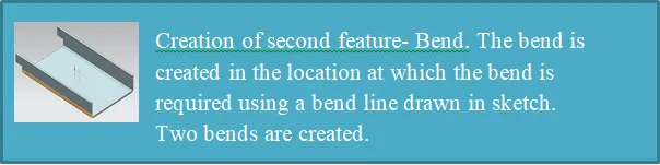
- BEND- This command is used to create bends at desired location in the sheet metal.Two bends are created in this project.
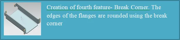
- BREAK CORNER- This command is used to round the edges of the flanges or tab, in this project it was used to round the edges of the flanges.
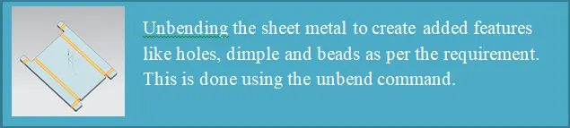
- UNBEND- This command was used to unbend the bent areas in the sheet metal to get the flattened sheet metal.
- HOLE- This command is used to create holes at desired location.This command is used to create four holes of screw size M2.
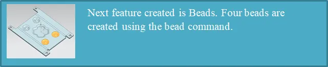
- BEAD- A bead is a long, drawn-out impression, which is impressed to increase stiffness in metal sheets or plates.This command is used to create four beads of 5mm diameter each.
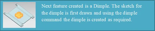
- DIMPLE- A dimple is created for the sketch using the dimple command. Dimple creates a feature that is done by lifting the material to a certain depth simulating a stamping process. This is used to give strength to the sheet metal as well as an aesthetic look.A dimple of depth 1mm is created.
- REBEND- This command is used to rebend the unbent areas to obtain the bend features and also to obtain the final sheet metal part.
- FLAT PATTERN- this command to to create the flat pattern view which is needed for drafting and later manufacturing purpose for a sheet metal.
Final Design Model
Front View
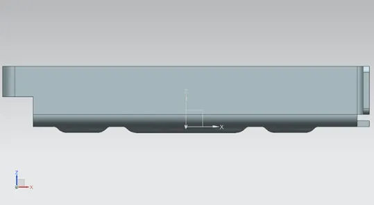
Side View (Right)
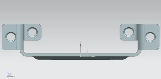
Isometric View
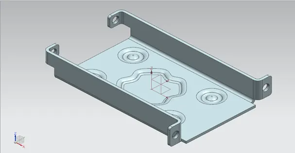
Top View
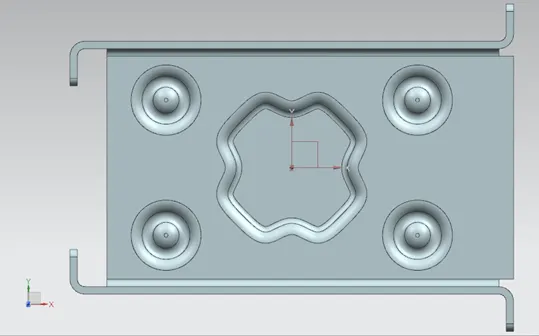
Flat Pattern
Detailed Drawing Sheet
CONCLUSION:
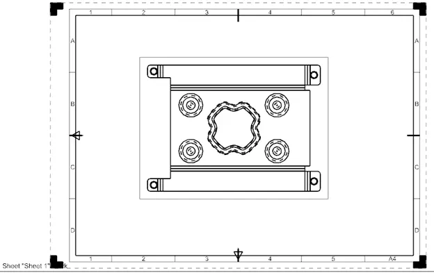
Thus the objective of designing a sheet metal casing in the NX CAD Sheet metal application is done successfully. The proper utilization of the commands to get the desired output, that is the flat pattern is achieved. The final draft is also derived from the flat pattern.