Advanced Sheet Metal Design Using NX Cad Challenge_1_Casing Design
Objective :
Create a sheet metal part Using advance sheet metal application in nx cad & Learn sheet metal design process.
Introduction :
In manufacturing industry sheet metal is one of the most versatile one. the main compositions are steel, alluminum and etc. sheet metal consists of variety of forms like plain flat sheets, embossed, ribbed, corrugated & perforated. the usage of sheet metal expands across many different industries including transportation,Aerospace and more.
Design Methodology :
The casing designed for this project consists of features like normal cut-outs, Bends, Flanges, Holes, Dimple & Beads. Every feature is designed in an order following the industrial procedure to keep the design intent. The design methodology used for this project can be summarized as depicted in the flow chart below.
Commands Used :
Sketch, Tab, Normal Cutout, Bend, Flange, Breake Corner, Unbend, Hole, Dimple, Bead, Rebend, Flat pattern, Draft.
Steps followed for creating the part :
- Sketch : sketch are the basic foundation of a design model. A base sketch is needed to perform most of the opertaions in sheet metal designing including tab,dimple,bead,hole etc can be created using the various sketch tools.
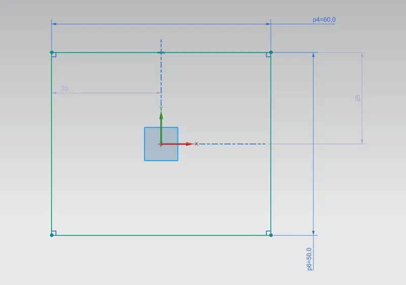
Rectangle of L=60mm & W=50mm
- Tab : Tabs are the basic feature in NX sheet metal designing process. Tab command in NX extrude a sketch along a vector by a thickness value
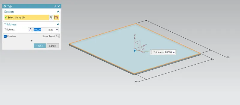
Base feature of casing design (1mm)
- Normal cut : this command extracts volumes from sheet metal by using sheet metal production principles. Cutting faces should be perpendicular to sheet metal surface.
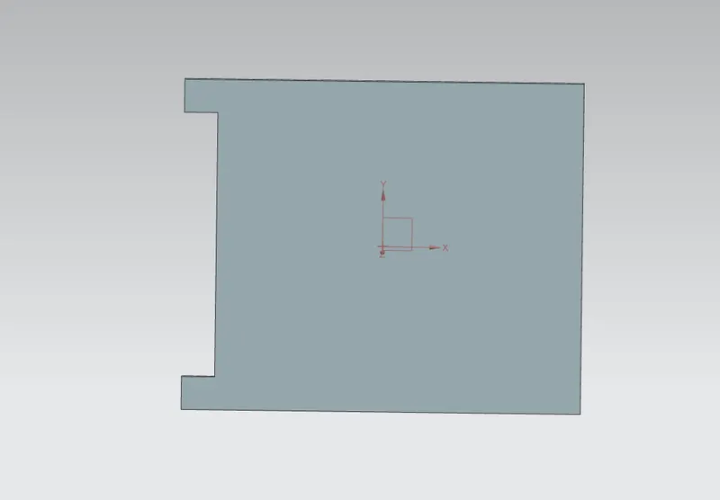
Using cutout command a cutout is performed at one side of the tab using a rectangle sketch of 40mm length and width of 5mm
- Bend : Bend command is used whenever a bend design is needed. It may be in any position or at any angle. A sketch is required to create a bend it can be either a straight line or a curve for this project of casing design two symmetric straight lines with respect to x axis are drawn for the bending curve.
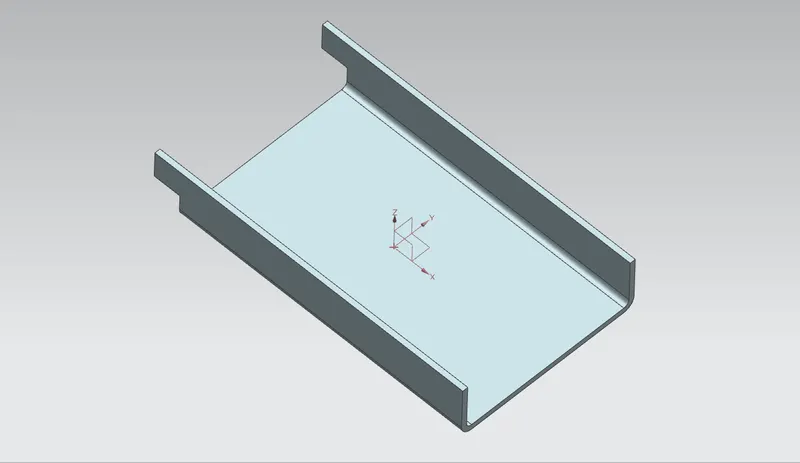
Both sides are bend at a length of 10mm & 1mm bend radius.
- Flange : This command consists of a face and a bend connected to an existing face along a staright edge. To add a flange feature, we select one more edges, and specify the size & position of the material added.
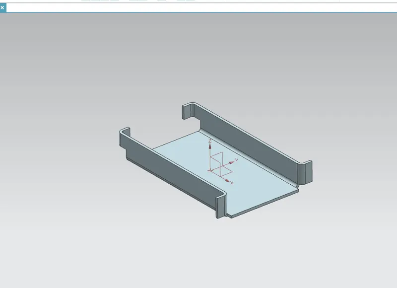
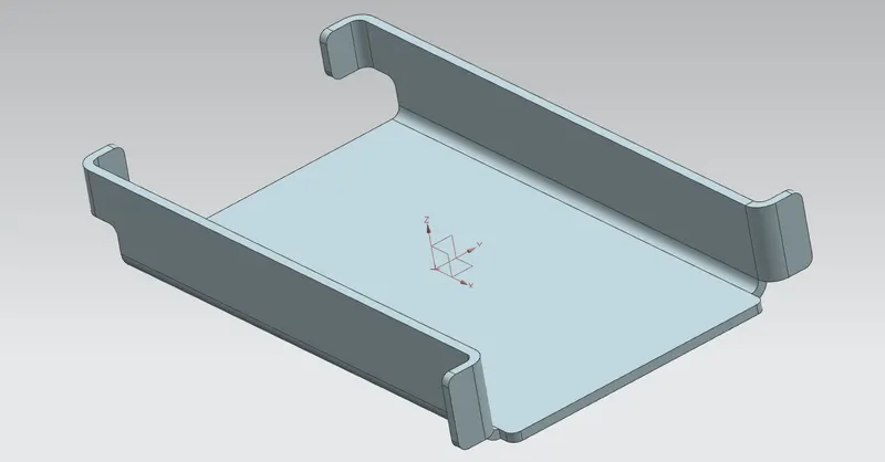
- Break the corner : Is used to round the sharp edges with user specified radius.
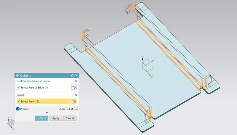
- Unbend : Unbend tool to unbend one or more curved surfaces as bends or curved walls to a flat configuration in as sheet metal part. for performing a Unbend feature its must to define a fixed planar face or edge. we can either select bend geometry individualy or automatically select all bend geometry.
- Hole : Hole feature can create either simple or counter bore or countersink or tapped holes. For this casing first the four points are sketched symmetric to x axis in position & the hole feature is applied.
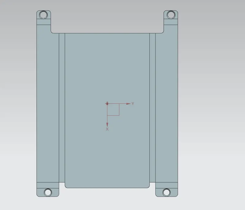
- Dimple: To create a raised dimple feature in a sheet metal part. The dimples can be placed on any flat surface including flanges and will extend in the direction of the face. The dimple feature will be governed by the settings defined in the options form. Dimples also helps sheet metal part to increase the stiffness.
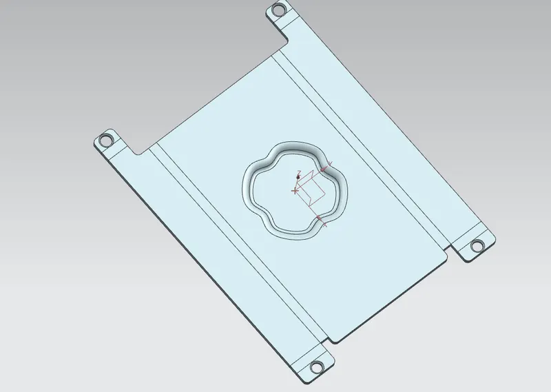
- Beads : These are the features added in the sheet metal components in order to increase the stiffness of the material. Beads require sketches to perform. It can be either a opened or closed profile. For this casing design project, four small beads are applied in symmetric position.
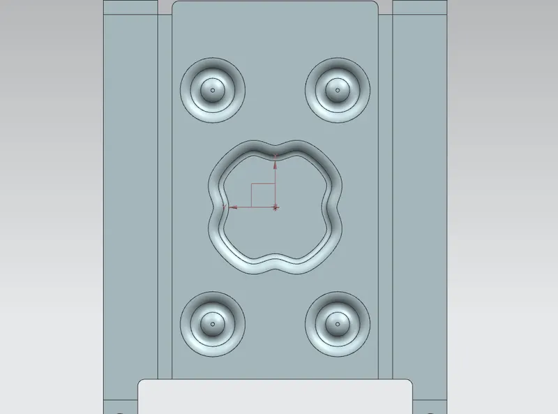
A bead of 5mm dia is created and mirrored the remaining 3 deads.
- Rebend : This command is used to bend the unbend parts along with the features applied after unbend.
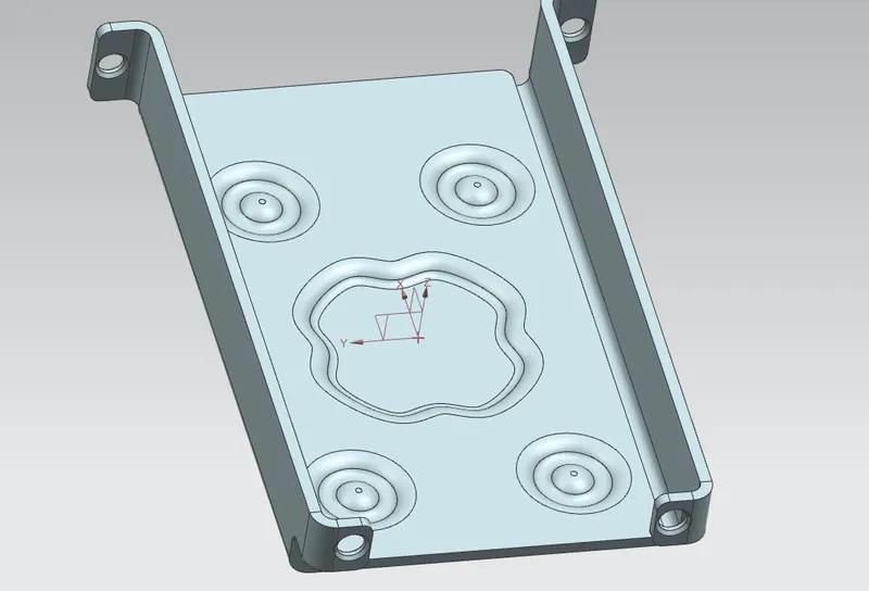
- Flat pattern : Flat pattern is the representation of the entire sheet metal component in the 2D form with all the bends, cut-outs, Holes & additional features in the form of lines or edges.
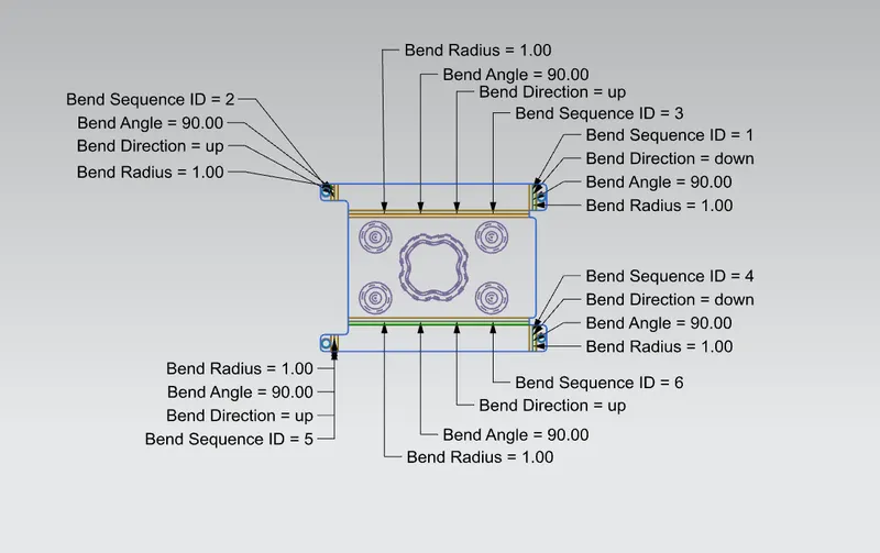
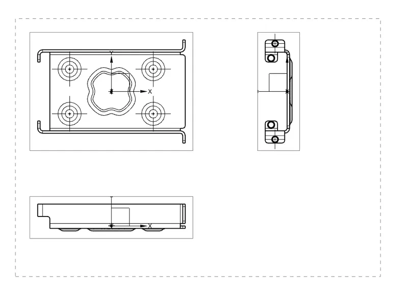
- Draft : after the modeling, the manufacturing of the component a technical 2D drawing of the component with accurate dimensions or scales denoted. For achieving this we are using the command draft Here a draft is created with a scale 2:1 & Using A4 size