Advanced Sheet Metal Design Using NX Cad Challenge_1_Casing Design
Advanced Sheet Metal Design Using NX Cad Challenge_1_Casing Design
OBJECTIVE: To design an advanced casing using the sheet metal application in Siemens NX.
Introduction
Sheet Metal Design is a vast domain in the design of any sheet metal industry, it is used in many sectors including the aeronautics & automotive sectors, in this sheet metal casing design we will look at the design approach using NX (CAD) SOFTWARE through various design, images, explanation, and images.
Design Methodology
- Select a new file in NX cad.
- Create Tab with Reference Sketch.
- Create advanced flanges on the edges of bends created in the previous step.
- Bending operation is done on side of the tab behind the cutout.
- on the tab created as a sketch to perform normal cut-out operation.
- Unbend the Sheetmetal by using unbend command.
- Add the holes required by using the Hole command.
- Sketch is created on the Surface of the tab to perform dimple operation.
- Studio Spline option is selected to create a spline curve.
- Rebend the Sheetmetal By using Rebend command.
- Beads also created with reference to holes where placed at required points Dimple operation with reference to Spline curve.
- Rotated Spline curve to 45 degrees.
- final product was achieved as per the inputs.
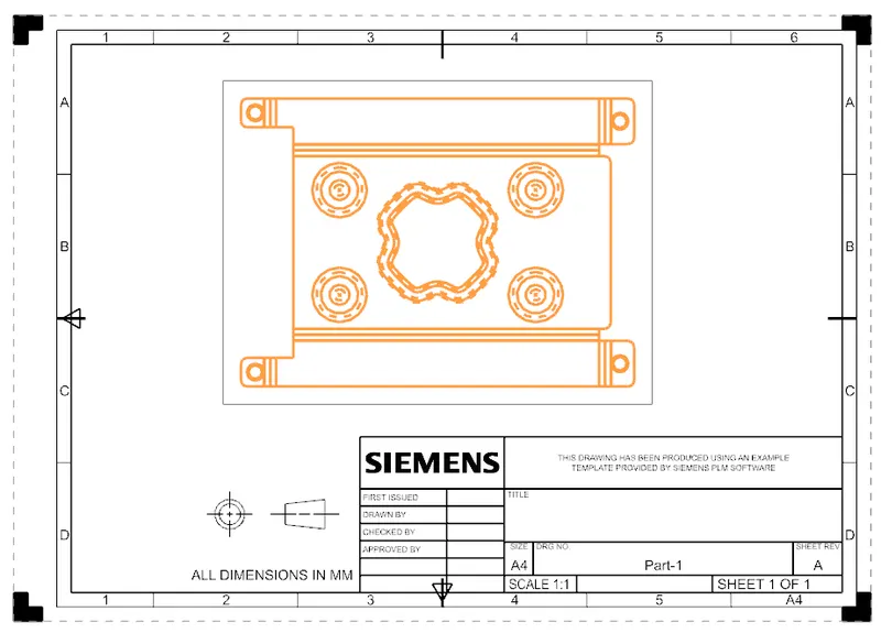
- Final Touch up was given in Drafting Sheet with a suitable Scale.
DESCRIPTION:
Sketch:- It’s a basic command to draw 2d models.
Tab:- A command to add parameters/ thickness to a Sketch
Bend:- It’s an operation to bend the tab at a particular position with reference
Flange:- It’s an operation to extend a sheet metal to one of the edges of a tab
UNBEND:- It’s a command used to flatten the created 3d model taking one face as a stationary face.
HOLE:- It’s a command used to create different types of holes like tapping and normal drilling, on the Surface of a Sheet metal.
DIMPLE:- It is a projection command of a particular shape with reference to a sketch with a certain depth.
BEAD:- It is also the type of projection to deform the shape at a certain point with reference to the sketch and also gives strength to the material.
REBEND:- This command is used to re-bend the already flattened sheet metal.
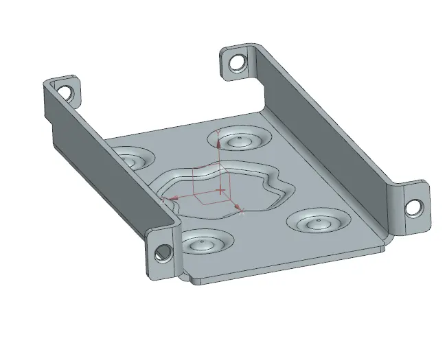
Iso Metric View
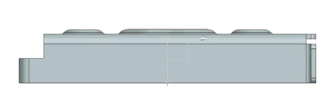
Side View
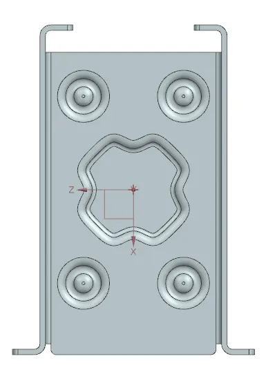
Top View
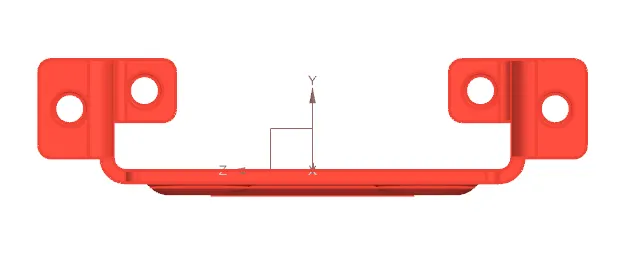
Front View
Detailed Drawing
CONCLUSION:-
This challenge help me to know about the application of various commands in advanced sheet metal and by using given inputs i am able to get the final product.